Subpart C – Track Geometry
§ 213.51 Scope
This subpart prescribes requirements for the gage, alinement, surface of track, and the elevation of outer rails and speed limitations for curved track
Guidance. See the following figure for an illustration of basic track geometry concepts.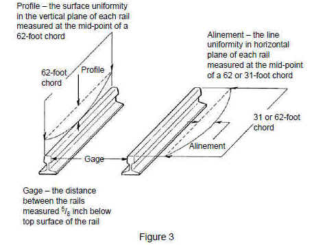
§ 213.53 Gage
53(a) Gage is measured between the heads of the rails at right angles to the rails in a plane five-eighths of an inch below the top of the rail head.
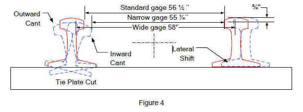
Guidance. See the following figure for an illustration of gage measurements.
53(b) Gage must be within the limits prescribed in the following table:
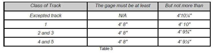
Guidance. This rule establishes the minimum and maximum limits for gage on all tracks and differentiates with the authorized speed, including a maximum gage dimension of 4 feet 10¼ inches for track in excepted status under § 213.4.
Inspectors will make measurements at sufficient intervals to assure that track is being maintained within the prescribed limits. Particular attention should be given to track gage in turnouts or locations where high lateral train forces are expected or evident. These areas include the curved closure rails, the toe and heel of frogs, the curved track behind the frog and several feet ahead of the switch points.
Where line or surface irregularities are observed by the inspector, the gage should be measured. Remember to look for evidence of lateral rail movement as required in § 213.13.
An accurate standard track gage device or a rule graduated in inches is an acceptable measuring device. Gage not within the specified limits of the TSS is in noncompliance.

§ 213.55 Alinement
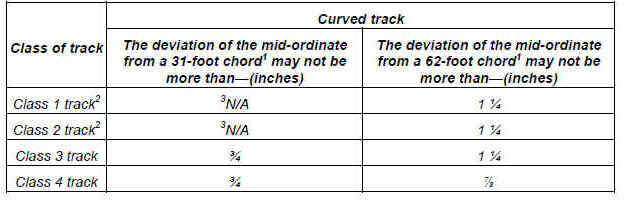
(a) Except as provided in paragraph (b) of this section, alinement may not deviate from uniformity more than the amount prescribed in the following table:
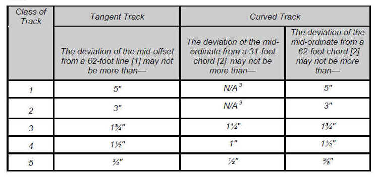
Guidance: This paragraph establishes the maximum alinement deviations allowed for tangent and curved track in Classes 1 through 5 track.
Alinement is the variation in curvature of each rail of the track. On tangent track, the intended curvature is zero; thus, the alinement is measured as the variation or deviation from zero. In a curve, the alinement is measured as the variation or deviation from the "uniform" alinement over a specified distance. The inspector should note that the procedures for determining uniformity in Classes 6 through 9 are similar to the procedures described below. However, there are differences in the spacing of the stations and the application of the chord measurements.
The point of greatest alinement deviation usually can be detected visually or may be located by moving the chord along the track in increments until the point with maximum deviation is found. In curves, the mid-ordinate, alternatively called mid-chord offset (MCO), require "stations" to be marked at regular intervals on the high rail in both directions from the point in question. In tangent track, the MCO is measured directly with a 62-foot chord and graduated ruler. In curves, a 62-foot chord is used in Classes 1 through 5 and a 31-foot chord is also used in Classes 3 through 5. The term MCO is used interchangeably for "mid-ordinate" and "mid-offset" and represents the distance from the rail to the chord at the mid-point of the chord. For curves in Classes 3 through 5 track, an alinement defect may be in noncompliance with either the maximum limits for the 31-foot chord or the 62-foot chord, or both. A 31-foot chord is particularly necessary for determining short alinement deviations. Inspectors must be aware that a 62-foot chord may be "blind" to short alinement conditions, whereby a 31-foot chord can detect those noncomplying conditions. See the following figure.

In Classes 3 through 5, both the 31-foot and 62-foot chords must be used, and corresponding measurements must be calculated to determine compliance with the required alinement thresholds. If alinement defects are found using both the 31-foot and the 62-foot chord, the inspector should report the item as one defect and note that the defect does not comply with the requirements for the second chord, e.g., "1¾ inches alinement deviation on curved track for 62-foot chord. Note: 1⅜ inches alinement deviation for 31-foot chord at this location."
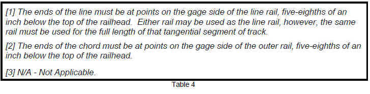
The chord line (string) will be stretched and held taut between two points on the rail, five-eighths inch below the top running surface of the rail. Measure the MCO between the rail and the string with a graduated ruler, using blocks to compensate for shallow curvature and special trackwork, if necessary.
Since a true tangent has zero MCO, the measurement taken can be compared directly to the alinement table under § 213.55 to determine compliance. On a curve of constant curvature or each arc of a compound curve, mid-ordinates at all station points are equal when measured from chords of equal length, exclusive of spirals. MCOs, when measured from chords of equal length, are nearly proportional to the degree of curvature.
Degree of curvature is the angle subtended at the center of a simple curve by a 100-foot chord. Degree of curvature can be conveniently measured using either a 31- or a 62-foot chord. Obtaining the degree of curvature coupled with the average elevation in the area in question is necessary to determine maximum authorized speed. Please refer to § 213.57 for a discussion on the determination of curvature.
Deviation of alinement on a curve requires determination of the MCO over a specified number of stations and the average of those values. The difference between the MCO at the point of concern and the average must not exceed the maximum deviation specified in the table in § 213.55(a).
An optional method to determine average alinement includes 17 stations spaced at 15 feet 6 inches (see table below). For curves in Classes 3 through 5, it is necessary to determine compliance with the requirement for the maximum deviation of the MCO from a 31-foot chord in addition to the 62-foot chord. The following figure illustrates the method to determine alinement deviation using both chords.
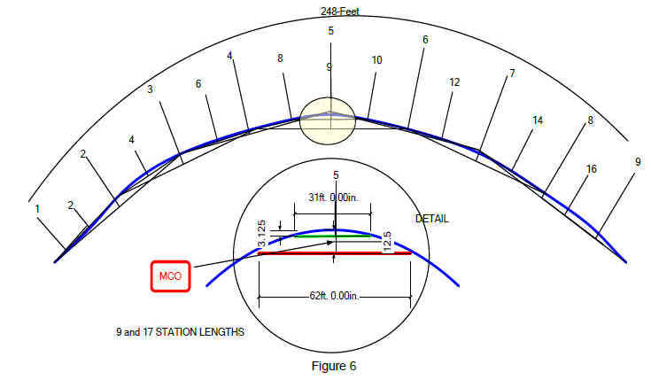
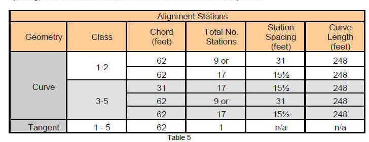
When using the above procedures, the distance between the first and last MCO will be 248 feet. However, note that in order to measure the MCO at the first and last stations, the inspector must place the end of the string a station beyond the first and last one measured. As a reference, the following table summarizes the acceptable proper chords, station spacing, and number of stations to determine alinement compliance.
As previously indicated, the suspected alinement location in a curve body is calculated by measuring an equal number of stations on each side of the area in question. For the majority of occurrences, averaging the MCOs on both sides of the location in question will develop sufficient data to determine “uniform alinement.” However, if the location in question is close to or in a spiral, uniformity must be determined in a different manner. If the location is located at the portion of a curve body close to a spiral, measure the stations in the curve body only. That is, shift the averaging area sufficiently so that none of the MCOs are in the spiral.
When measuring the body of a curve with a length that is less than the distance spanned by the required number of stations, reduce the numbers of stations accordingly. When measuring a compound curve, it will be necessary to measure the MCOs within a sufficient portion of the entire curve to determine where the curve bodies exist. Treat each curve body as a separate curve and be governed by the above instructions.
Over the years, railroads have traditionally used a 31-foot chord to determine MCOs for higher degree curves. Although it is more difficult to measure from the rail to the MCO at high degree curves, the inspector must determine alinement compliance in accordance with both the 62 and 31-foot chords described in this section.
In spirals, the alinement gradually changes from tangent to the full degree of curvature at the curve body. The projected MCO values must be established, which is a function of actual curvature at a specific point on the spiral, curvature (of the curve body) and spiral length. The first step is to determine the tangent to spiral (TS) and spiral to curve (SC). There are several ways to determine TS and SC. An inspector can reference geometry car measurements, if available. Alternatively, he/she can measure alinement MCOs along the entire spiral length, ensuring a sufficient distance into the adjoining curve body and tangent track to accurately locate TS and SC.
Once TS and SC are determined and marked, the actual curvature at any point on the spiral can be easily calculated with known curvature of the curve body and spiral length - the distance between TS and SC. For example, at a point 100 ft from TS on a spiral, the curvature is
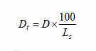
Where
D
i = the actual curvature at the ith point on the spiral, degreesD = curvature of the curve,
degrees,L
s = spiral length, ftWith known spiral curvature, the 31-ft or 62-ft MCOs can be projected based on curvature-to- MCO extrapolation (e.g. 1 degree curvature yields approximately 1" 62-ft MCO or ¼" 31-ft MCO).
Plot the measured values along with projected values in a graph or construct a table of the measured and projected values. The deviation at the point of concern will be the difference between the measured and the projected MCO values. Use the curve values from the alinement table to determine compliance in spirals.
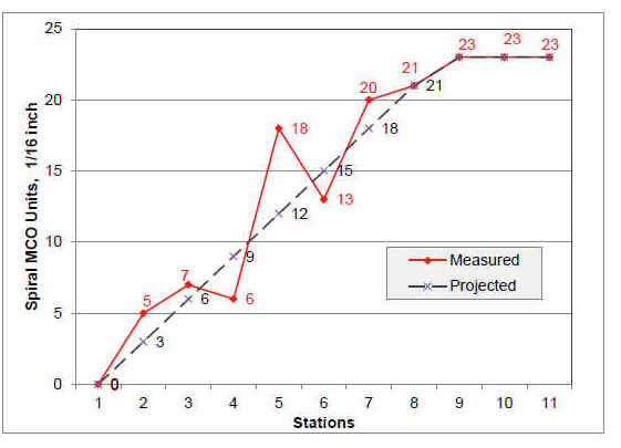
The following figure represents a hypothetically case where the spiral length is 248 ft. (9 stations spaced at 31 ft). The chart would approximate a 1.44 degree curve whose curvature is gradually increased from 0 (at TS) to 1.44 degrees (at SC). The figure shows a spiral calculation for 62-foot chord with MCO units in 1/16-inch increments. A similar analysis is required for 31-foot chord for Classes 3 through 5. At Station 5, the measured value is 18 units (1⅛ inches) and the projected value is 12 units (¾ inch); therefore, the deviation from uniformity is 6 units (⅜ inch).
For long spirals, especially in higher speed curves, it could become arduous to measure the entire spiral. Where it’s feasible to determine the approximate locations of TS and SC, the inspector can opt to measure several stations (no more than 6 for either TS or SC) around the two pre-identified areas to pinpoint TS and SC to determine the spiral length. The inspector can then calculate the actual spiral curvature using the equation shown above. This actual spiral curvature is then extrapolated into projected/alimenent MCO (1 degree to 1" 62-ft MCO or ¼" 31-ft MCO). The inspector can take one single MCO measurement at the point of concern to determine compliance. The difference between the projected and measured alinement will be used to assess compliance, referencing the allowable values from the alinement table.
(b) For operations at a qualified cant deficiency, Eu, of more than 5 inches, the alinement of the outside rail of the curve may not deviate from uniformity more than the amount prescribed in the following table:
Guidance:
The guidance for paragraph 55(a) also applies to this paragraph. However, the limits in the table of this paragraph applies only to operations at a qualified cant deficiency of more than 5 inches, and to outside rail of the curve. . Note that the limits for Class 4 and lower track have been tightened – most notably for Class 1 and 2 track 62-ft MCO. These limits were established based on computer simulations to provide sufficient margins of safety, as higher cant deficiency operations will result in higher lateral wheel loads.As for any operation involving more than 5 inches of cant deficiency, the track owner or railroad must have the necessary FRA approval/documentation showing that the operations are qualified for a cant deficiency higher than 5 inches.
If the track owner or railroad, in response to an alignment exception to table 55(b), has posted a speed restriction which no longer corresponds to a cant deficiency of more than 5 inches, the inspector should use the limits in table 55(a) to assess alignment compliance.
§ 213.57 Curves; elevation and speed limitations
57(a) The maximum elevation of the outside rail of a curve may not be more than 8 inches on track Classes 1 and 2, and 7 inches on track Classes 3 through 5. The outside rail of a curve may not be lower than the inside rail by design, except when engineered to address specific track or operating conditions; the limits in §213.63 apply in all cases.
Guidance: The term "elevation of the outside rail" is relevant to the inside rail. In literature and in practice, it is also referred as superelevation. This paragraph does not imply that more than 6 inches of superelevation is recommended in a curve; rather the paragraph limits the amount of superelevation in a curve to control the unloading of the wheels on the outer rail, especially at low speeds. The limits establish the maximum superelevation at any point on the curve; which may not be more than 8 inches on Classes 1 and 2, and 7 inches on Classes 3 through 5. In curves, superelevation is measured by subtracting the relative difference in height between the top surface (tread) of the inside (low) rail from the tread of the outside (high) rail. Both this section and § 213.63 limit the amount of reverse elevation (outside rail lower than the inside rail). While the table in § 213.63 permits reverse elevation on a curve, the Vmax formula must also be checked when reverse elevation is encountered. The inspector must substitute a negative number for the actual elevation in the formula as discussed below. The Vmax formula applies only in the body of a curve.
The phrase "except when engineered to address specific track or operating conditions" is intended to address special cases, such as a turnout that comes off the high rail in a curve, to allow reverse elevation to be designed into the curve out of necessity and for safety reasons.
57(b) The maximum allowable posted timetable operating speed for each curve is determined by the following formula—
![]()
Where—
Vmax = Maximum allowable posted timetable operating speed (m.p.h.).
Ea = Actual elevation of the outside rail (inches).1
1Actual elevation, Ea, for each 155-foot track segment in the body of the curve is determined by averaging the elevation for 11 points through the segment at 15.5-foot spacing. If the curve length is less than 155 feet, the points are averaged through the full length of the body of the curve.
Eu = Qualified cant deficiency2 (inches) of the vehicle type.
2If the actual elevation, Ea, and degree of curvature, D, change as a result of track degradation, then the actual cant deficiency for the maximum allowable posted timetable operating speed, Vmax, may be greater than the qualified cant deficiency, Eu. This actual cant deficiency for each curve may not exceed the qualified cant deficiency, Eu, plus 1 inch.
D = Degree of curvature (degrees).3
3Degree of curvature, D, is determined by averaging the degree of curvature over the same track segment as the elevation.
Guidance:
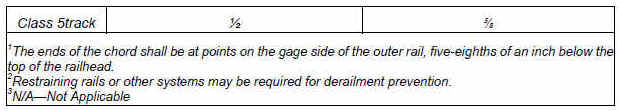
Paragraph (b) prescribes the formula to be used to determine the maximum train speed in curves based on average curve alinement in degrees, qualified cant deficiency, and the amount of superelevation at the same location.A railroad car traveling around a curve is subjected to an outward horizontal centrifugal force that acts conceptually through a car’s center of gravity away from the center of the curve and tends to overturn the car by directing its weight toward the outside rail. To counteract the centrifugal force, the outer rail is elevated over the lower rail, or superelevated. In effect, the combined effect of centrifugal force and weight produces a resultant force that is intentionally moved toward the center of the track. A balanced (equilibrium) condition implies the vertical forces on each rail are equal. The following figure illustrates three scenarios for the given curvature and superelevation. The chart in the center indicates that if the vehicle is traveling at 42 m.ph., the equilibrium will be achieved. The chart on the left is an overbalanced scenario, in which a net inward acceleration (weight shifting to low rail) will result as the vehicle travels slower than 42 m.p.h. The chart on the right represents an underbalanced scenario, in which a net outward acceleration (weight shifting to high rail) will result as the vehicle travels fasters than 42 m.p.h. Using the vMax formula in this example, 3 inches of unbalance allows a maximum posted timetable speed of speed of 54 mph. Tolerance for localized degradation of up to 1 inch (Eu+1) results in a maximum speed of 57 mph. (§213.57(a) would apply to overbalance)
In practice, railroads generally do not operate trains at balanced speed; that is, train speeds are set to move the resultant force toward the outer rail, resulting in an unbalance, typically less than 3 inches. Unbalance, also commonly referred as cant deficiency, is the theoretical amount of elevation that would have to be added to the existing elevation to achieve a balanced condition. The TSS for Classes 1 through 5 limits the amount of unbalance to 3 inches, except that higher unbalance is permitted for authorized and approved equipment types. Appropriate vehicle/track system qualification tests will apply to operations at cant deficiencies higher than 3 inches.
Safe curving speeds are dependent on the engineering characteristics of the specific equipment involved, as well as the track conditions. Equipment factors, such as center of gravity, suspension characteristics, and reaction to wind and other factors, are considered when FRA makes a decision to approve a particular level of cant deficiency for specified equipment.
Track inspectors can use the formula to assess compliance in two ways:
1) Calculating cant deficiency by inserting the posted timetable speed, actual superelevation (Ea), and curvature (D) at the time of inspection. If the resulting actual cant deficiency is higher than the qualified cant deficiency, there is a potential limiting speed defect.
2) Calculating maximum allowable operating speed by inserting the actual elevation (Ea), and curvature (D) at the time of inspection and qualified cant deficiency (Eu). If the resulting speed is lower than the posted timetable speed, there is a potential limiting speed defect.
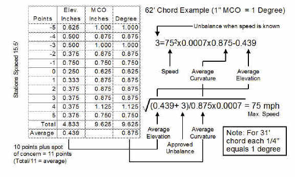
Footnote 1 clarifies the procedure to establish the actual elevation Ea which states that 11 points at 15.5-foot spacing through the 155-foot evaluation segment will be averaged. In calculating elevation, 10 measurements are taken in addition to the point of concern — 5 on each side—so that a total of 11 points are actually averaged.
The method of 11-point average over 155-foot segment at 15.5-foot station spacing applies to both 31- and 62-foot chords and to the curve body only. If a curve’s length is less than 155 feet, the measurements are averaged over the full length of the curve. In order to determine the average curvature, inspectors must calculate the degree of curvature based on the chord length used (either 31 or 62 feet) and the MCO measured at each station. For a 31-foot chord, the degree of curvature is determined by multiplying the MCO by a factor of four (e.g., one-quarter inch equals 1 degree). For a 62-foot chord, a one-to-one relationship exists (e.g., 1 inch equals 1 degree).
Footnote 2 permits the vehicle type to operate at the approved cant deficiency plus 1 inch, if the actual elevation, Ea, and the degree of track curvature, D, have changed as a result of track degradation. The note is intended to provide a tolerance to account for the effects of local superelevation or curvature conditions on Vmax that may result in the actual cant deficiency exceeding the approved level for the equipment. The intent is to allow this tolerance for "local crosslevel or curvature conditions" that result in track degradation below the maintenance limits of the track owner/railroad. The footnote is not intended to provide a tolerance to be factored into the maintenance limits themselves. For example, if the "maximum allowable posted timetable operating speed" is based on a Vmax corresponding to 3 inches of cant deficiency, the track owner/railroad should not establish maintenance practices that are intended to result in operation of equipment at a speed that produces up to 4 inches of cant deficiency. Yet in this example, should the equipment actually operate at a speed that produces over 3 inches of cant deficiency due to track degrading below the intended maintenance limits of the track owner/railroad, the track owner/railroad should not be penalized merely because the cant deficiency exceeds 3 inches.
Caution need to be paid when exercising this provision. Because a tolerance is now part of the regulation, not all exceedances are actual defects (i.e., actual instances of non-compliance). The Inspector should only record the condition as a defect if there is evidence that the maintenance practices of the track owner/railroad created a condition where the actual amount of cant deficiency exceeded the approved value. In this case FRA expects the track owner/railroad to take appropriate remedial action. The Inspector should consider writing a recommendation for civil penalty if the level of cant deficiency based on the maximum speed, elevation, and curvature exceeds the approved value, Eu, by more than 1 inch. When the actual cant deficiency is found to exceed the approved level, there are many scenarios that could involve compliance or non-compliance with the regulation, and all of these different scenarios cannot be easily described here. The Inspector should consider multiple factors when determining whether to assess a defect or recommend a violation. For example, if the Inspector can establish that a track has been recently machine-tamped and that it was not possible for the track to have degraded to the level of causing an exceedance of the approved cant deficiency in the time period after the tamping, the Inspector may assess a defect. In another example, if the track owner/railroad voluntarily performs spot maintenance on a curve, typically through spot-tamping, to bring the curve to uniformity (in terms of curvature and elevation), and the amount of cant deficiency still exceeds the approved level by a nominal amount, the Inspector should exercise his or her discretion whether to assess a defect. The Inspector should consider assessing a defect when the exceedance is close to the maximum tolerance, which leaves little room for further track degradation. In all cases, if the Inspector cannot determine whether a condition is out of compliance, or whether to assess a defect or recommend a civil penalty, he or she should consult with the Regional Track Specialist.
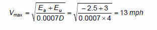
In addition to the limitations on reverse elevation contained in the table in § 213.63, the Vmax formula limits the maximum authorized speed on a curve. Reverse elevation occurs when the inside rail is higher than the outside rail; that is usually the unintended consequence of track degradation. The condition can also occur where a turnout has been installed in a main track (e.g., an equilateral turnout constructed in a left-hand curve). Calculation of the maximum authorized speed for the curve with negative elevation is performed in the same manner as one with positive elevation. For example, the maximum authorized speed is approximately 13 mph for a curve segment with an average curvature of 4 degrees and 2½ inches of reverse elevation (both calculated over the 155 foot window or the length of the curve), the calculation for 3 inches of unbalance would be as shown below:
57(c) All vehicles are considered qualified for operating on track with a cant deficiency, Eu, not exceeding 3 inches. Table 1 of appendix A to this part is a table of speeds computed in accordance with the formula in paragraph (b) of this section, when Eu equals 3 inches, for various elevations and degrees of curvature.
Guidance: This paragraph provides that all vehicle types are considered qualified for up to 3 inches of cant deficiency.
57(d) Each vehicle type must be approved by FRA to operate on track with a qualified cant deficiency, Eu, greater than 3 inches. Each vehicle type must demonstrate, in a ready-for-service load condition, compliance with the requirements of either paragraph (d)(1) or (2) of this section.
(1) When positioned on a track with a uniform superelevation equal to the proposed cant deficiency:
(i) No wheel of the vehicle type unloads to a value less than 60 percent of its static value on perfectly level track; and
(ii) For passenger cars, the roll angle between the floor of the equipment and the horizontal does not exceed 8.6 degrees; or
(2) When operating through a constant radius curve at a constant speed corresponding to the proposed cant deficiency, and a test plan is submitted to and approved by FRA in accordance with §213.345(e) and (f):
(i) The steady-state (average) load on any wheel, throughout the body of the curve, is not less than 60 percent of its static value on perfectly level track; and
(ii) For passenger cars, the steady-state (average) lateral acceleration measured on the floor of the carbody does not exceed 0.15g.
Guidance: The rule does not limit maximum level of cant deficiency in track Classes 1 through 5. However, the equipment must satisfy the requirements of this section. Consistent with the higher-speed standards in § 213.329, the requirements limit (1) vertical wheel load remaining on the raised wheels to no less than 60 percent of their static level values and (2) carbody roll for passenger cars to no more than 8.6 degrees with respect to the horizontal when the vehicle is standing (stationary) on track with a uniform superelevation equal to the proposed cant deficiency. The amount of superelevation will be the proposed cant deficiency.
For example, if the proposed cant deficiency is 5 inches, the superelevation used for demonstrating compliance with this paragraph is also 5 inches.
The requirements in paragraph (d) may be met by either static or dynamic testing. The static lean test limits the vertical wheel load remaining on the raised wheels and the roll of a passenger carbody with respect to the horizontal plane to the thresholds mentioned above. The dynamic test limits the steady-state vertical wheel load remaining on the low rail wheels to no less than 60 percent of their static level values and limits the lateral acceleration in a passenger car to 0.15g steady-state, when the vehicle operates through a curve at the proposed cant deficiency. This 0.15g steady-state lateral acceleration limit in the dynamic test is intended to provide consistency with the 8.6-degree roll limit in the static lean test, which corresponds to the lateral acceleration a passenger would experience in a standing vehicle with its carbody rolled 8.6 degrees with respect to the horizontal.
Measurements and supplemental research have indicated that a steady-state, carbody lateral acceleration limit of 0.15g is considered to be the maximum, steady-state lateral acceleration above which jolts from vehicle dynamic response to track deviations can present a hazard to passenger safety. While other FRA vehicle/track interaction safety criteria principally address external safety hazards that may cause a derailment, such as damage to track structure and other conditions at the wheel/rail interface, the steady-state, carbody lateral acceleration limit specifically addresses the safety of the interior occupant environment. This steady-state, carbody lateral acceleration will result in a lateral force, pulling passengers to one side of the carbody. It is not the same as sustained, carbody lateral oscillatory accelerations, or continuous side-to-side oscillations (hunting) of the carbody in response to track conditions, which could exist on both curved and tangent track.
57(e) The track owner or railroad shall transmit the results of the testing specified in paragraph (d) of this section to FRA's Associate Administrator for Railroad Safety/Chief Safety Officer (FRA) requesting approval for the vehicle type to operate at the desired curving speeds allowed under the formula in paragraph (b) of this section. The request shall be made in writing and contain, at a minimum, the following information—
(1) A description of the vehicle type involved, including schematic diagrams of the suspension system(s) and the estimated location of the center of gravity above top of rail;
(2) The test procedure,4 including the load condition under which the testing was performed, and description of the instrumentation used to qualify the vehicle type, as well as the maximum values for wheel unloading and roll angles or accelerations that were observed during testing; and
4The test procedure may be conducted whereby all the wheels on one side (right or left) of the vehicle are raised to the proposed cant deficiency, the vertical wheel loads under each wheel are measured, and a level is used to record the angle through which the floor of the vehicle has been rotated.
(3) For vehicle types not subject to parts 229 or 238 of this chapter, procedures or standards in effect that relate to the maintenance of all safety-critical components of the suspension system(s) for the particular vehicle type. Safety-critical components of the suspension system are those that impact or have significant influence on the roll of the carbody and the distribution of weight on the wheels.
4 The test procedure may be conducted whereby all the wheels on one side (right or left) of the vehicle are raised to the proposed cant deficiency, the vertical wheel loads under each wheel are measured, and a level is used to record the angle through which the floor of the vehicle has been rotated.
Guidance:
This paragraph clarifies the submittal requirements to FRA to obtain approval for the qualifying cant deficiency of a vehicle type. The load condition under which the testing is performed is required to be included in the description of the test procedure. The paragraph also includes the requirement for submitting suspension system maintenance information.For vehicle types not subject to 49 CFR parts 238 or 229, such as a freight car operated in a freight train, the requirement for submitting suspension system maintenance information only to safety-critical components.
Footnote 4 specifies more detailed requirements if the cant deficiency requirement of 57(d)(1) is satisfied through static lean test.
57(f) In approving the request made pursuant to paragraph (e) of this section, FRA may impose conditions necessary for safely operating at the higher curving speeds. Upon FRA approval of the request, the track owner or railroad shall notify FRA in writing no less than 30 calendar days prior to the proposed implementation of the approved higher curving speeds allowed under the formula in paragraph (b) of this section. The notification shall contain, at a minimum, identification of the track segment(s) on which the higher curving speeds are to be implemented.Guidance: The paragraph requires that a track owner/railroad notify FRA prior to the implementation of the approved higher curving speeds. The paragraph also clarifies that in approving the request made pursuant to paragraph (e), FRA may impose conditions necessary for safely operating at the higher curving speeds.
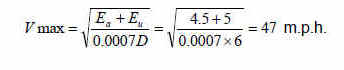
Where FRA has approved higher levels of unbalance, it becomes imperative that the inspector monitor the maximum authorized speeds based on the approved unbalance. The calculation of the maximum authorized speed for a particular segment of track involves the substitution of the approved unbalance in the Vmax formula. For example, if FRA approved 5 inches of cant deficiency for a particular type of equipment, the maximum curving speed for a 6-degree curve segment with 4½ inches of elevation would be calculated as follows:
To determine an enforcement action, it is also necessary for the inspector to determine the actual unbalance based on the speed that the railroad is operating around the curve and the actual track conditions. In order to calculate the unbalance, the inspector must solve the following formula, which is the same Vmax formula represented in a different form:
![]()
For example, if the railroad was operating around a curve at 89 m.p.h. and the inspector determined, by field measurements, that the average curvature and average elevation for a particular curve segment were 2 ¼ degrees and 5½ inches, respectively. The unbalance would be calculated as follows:
![]()
In this example, the operating speed has resulted in a cant deficiency of 6.9 inches, which is 1.9 inches over the approved level of 5 inches. As mentioned in the guidance for 57(b), the inspector should consider a recommendation for civil penalty.When vehicle types have been approved by FRA for curving speeds producing more than the approved level but not exceeding by more than 1 inch, inspectors may consider writing a defect according to the guidance in 57(b).
The following figure illustrates the relationship between curvature, elevation, and speed.
57(g) The documents required by this section must be provided to FRA by:
(1) The track owner; or
(2) A railroad that provides service with the same vehicle type over trackage of one or more track owner(s), with the written consent of each affected track owner.
Guidance:
This paragraph states that either a track owner or a railroad (operator), e.g. Amtrak or other commuter railroads, providing services over trackage of more than one track owner with the same vehicle type may provide the required documents to the FRA. However, the operator must have consent of each track owner.By allowing the operator to submit the documents, FRA eliminates the potential of multiple submissions for the same vehicle type.
This paragraph is identical to two other provisions in § 213.329(g) - the subpart G counterpart to this section - and § 213.345(i).
213.57(h)(1) Vehicle types permitted by FRA to operate at cant deficiencies, Eu, greater than 3 inches but not more than 5 inches shall be considered qualified under this section to operate at those permitted cant deficiencies for any track segment. The track owner or railroad shall notify FRA in writing no less than 30 calendar days prior to the proposed implementation of such curving speeds in accordance with paragraph (f) of this section.
(2) Vehicle types permitted by FRA to operate at cant deficiencies, Eu, greater than 5 inches shall be considered qualified under this section to operate at those permitted cant deficiencies only for the previously operated or identified track segments(s).
Guidance:
This paragraph concerns vehicle types that have been previously permitted by FRA to operate at cant deficiencies, Eu, greater than 3 inches.Paragraph (h)(1) states these vehicle types previously approved by FRA to operate at cant deficiencies, E
u, between 3 and 5 inches are considered qualified under this section to operate at the approved cant deficiencies on any track segment. The rationale to allow this portability is that the requirements of this section are steady-state and do not directly reflect the "local" vehicle and the track interaction.Nonetheless, a provision in paragraph (h)(1) required that written notice be provided to FRA no less than 30 calendar days prior to the proposed implementation of such curving speeds on another track segment in accordance with paragraph (f) of this section. This notice is intended to identify the new track segment(s) so that FRA is aware of the proposed operation to ensure that appropriate permission has been provided for it, and for administering the requirements of this rule.
However, the provision in paragraph (h)(2) restricts the "portability" of cant deficiency qualification for vehicle types that have been permitted by FRA to operate at cant deficiencies, E
u, greater than 5 inches. Operation at cant deficiencies greater than 5 inches over other track segments must be newly qualified in accordance with this rule, consistent with the additional requirements for the safety of operations at cant deficiencies greater than 5 inches.213.57(i) For vehicle types intended to operate at any curving speed producing more than 5 inches of cant deficiency, the following provisions of subpart G of this part shall apply: §§213.333(a) through (g), (j)(1), (k) and (m), 213.345, and 213.369(f).
Guidance:
The paragraph applies to operations at cant deficiencies greater than 5 inches. The requirements for operations of more than 5 inches cant deficiency apply to all classes of track. These requirements are specified in §§ 213.333, Automated vehicle-based inspection systems, paragraphs (a) through (g), (j)(1), (k) and (m); 213.345, Vehicle/track system qualification; and 213.369, Inspection records, paragraph (f). These requirements are briefly summarized below. For complete guidance on § 213.333 and other provisions of subpart G please see Volume II, Chapter 2 of this manual.Section 213.333(a)(1) requires a Track Geometry Measurement System (TGMS) to be operated over Class 1 through 5 track that supports cant deficiency operations of more than 5 inches. The frequency for the TGMS inspections is at least twice per calendar year with not less than 120 days between inspections. Sections 213.333(b) through (e) list the TGMS system criteria. Section 213.333(f) continues to require that the track owner, within two days after the TGMS inspection, field verify and institute remedial action for all exceptions to the class of track. Section 213.333(g) requires the track owner or railroad to maintain a copy of the plot and the exception report for the required TGMS inspection. Section 213.333(j)(1) requires that a vehicle having dynamic response characteristics representative of other vehicles assigned to the service be operated over the route at the revenue speed profile. The vehicle shall be monitored for carbody accelerations with an onboard monitoring system at least once each calendar quarter. Section 213.333(k) describes the requirements for monitoring carbody lateral and vertical accelerations and track frame lateral acceleration. Section 213.333(m) requires the track owner or railroad to maintain a copy of the most recent exception records for the inspections required under paragraphs 333(j), (k).and (l).
(j) As used in this section—
(1) Vehicle means a locomotive, as defined in §229.5 of this chapter; a freight car, as defined in §215.5 of this chapter; a passenger car, as defined in §238.5 of this chapter; and any rail rolling equipment used in a train with either a freight car or a passenger car.
(2) Vehicle type means like vehicles with variations in their physical properties, such as suspension, mass, interior arrangements, and dimensions that do not result in significant changes to their dynamic characteristics.
Guidance: Paragraph (j) clarifies "vehicle" and "vehicle type." The paragraph is of particular importance when determining if a vehicle type is subject to the qualification requirements of this section. For example, a vehicle type with modified primary springs to improve performance at different speeds may be considered a new vehicle type and hence subject to the qualification requirements of this section.
§ 213.59 Elevation of curved track; (runoff)
59(a) If a curve is elevated, the full elevation must be provided throughout the curve, unless physical conditions do not permit. If elevation occurs in a curve, the actual minimum elevation must be used in computing the maximum allowable operating speed for that curve under §213.57(b).
Guidance: When determining whether curved track is in compliance with the TSS, inspectors should consider §§ 213.57, 213.59, and 213.63 in conjunction with one another. Because the language in § 213.59 is explanatory in nature and intertwined with the requirements in §§ 213.57 and 213.63, this section should not stand alone in support of an alleged violation. FRA Inspectors should cite either § 213.57 or § 213.63, whichever is most applicable.
59(b) Elevation must be at a uniform rate, within the limits of track surface deviation prescribed in §213.63 and it must extend at least the full length of the spirals. If physical conditions do not permit a spiral long enough to accommodate the minimum length of runoff, part of the runoff may be on tangent track.
Guidance:
Items to consider with respect to runoff include the following:• If elevation begins within the body of the curve rather than at the point of curve-spiral, the least average elevation that exists in the body of the curve will govern the allowable operating maximum speed throughout the full curve.
• Elevation at the end of curves, or between segments of compound curves, must be at a uniform rate within the limits of track surface deviations prescribed in the table under § 213.63.
• Particular attention must be given to the prescribed limits for difference in crosslevel between any two points less than 62 feet apart on spirals.
•
If physical conditions do not permit a spiral long enough to accommodate the minimum length of runoff, the runoff may be carried into the tangent. In these circumstances, the surface table parameters under § 213.63 will govern.• The actual minimum elevation and actual degree of curvature is determined by using the averaging techniques described under § 213.57.
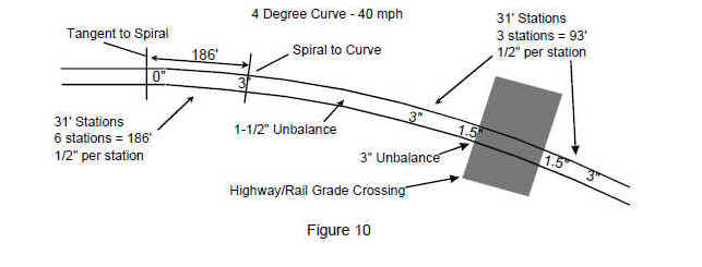
The following figure illustrates how a railroad can reduce superelevation in the body of the curve to accommodate a highway-rail grade crossing for unqualified equipment (3 inches unbalance).
§ 213.63 Track Surface
213.63(a) Except as provided in paragraph (b) of this section, each track owner shall maintain the surface of its track within the limits prescribed in the following table:
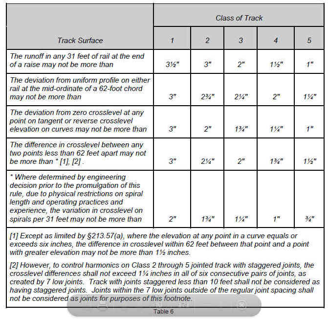
Guidance:
Track surface is the evenness or uniformity of track in short distances measured along the tread of the rails. Under load, the track structure gradually deteriorates due to dynamic and mechanical wear effects of passing trains. Improper drainage, unstable roadbed, inadequate tamping, and deferred maintenance can create surface irregularities. Track surface irregularities can lead to serious consequences if ignored.Allowable deviations in track surface include runoff at the end of a raise, deviation from uniform profile, deviation from zero crosslevel at any point on tangent or reverse crosslevel elevation on curves, and the difference in crosslevel between any two points less than 62 feet apart (referred as track warp), are specified in the track surface table. In addition, the table includes footnotes that address three special circumstances.
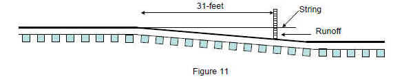
The first parameter in the table in this section refers to the runoff (ramp) in any 31-foot segment at the end of a raise where the track is elevated as a result of automatic or manual surfacing or bridge work. Conditions created by track degradation (e.g., settlement or frost heaves) are to be addressed using the uniform profile parameter, under this section. Trains encountering a ramp (up or down) will experience a vertical pitch or bounce if the change in elevation occurs in too short a distance. As in the more general profile parameter, damage to car components, undesirable brake applications or derailments may occur; especially when the vehicle experiences a lateral force such as a buff force. The following figure illustrates the measurement of the runoff of raised track.
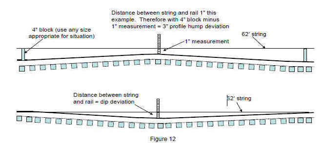
The second parameter, profile, relates to the elevation of either rail along the track. When trains encounter short dips or humps in the track it can result in vertical separation of couplers, broken springs, bolsters, and truck frames. Dips can result from mud spots, or develop at the ends of fixed structures (e.g., bridges, highway rail grade and track crossings). A profile is determined by placing the mid-point of a 62-foot chord at the point of maximum measurement, irrespective of vertical curves. A profile may also be a track "hump" caused by a frost heave or other occurrence. The following figure illustrates the measurement of profile conditions.
voids to the mid-ordinate distance, according to § 213.13 (dynamic loading).
When encountering a hump (e.g., frost heaves over culverts), place two uniform (reference offset) blocks on top of the running rail. Stretch (taut) a 62-foot string over the blocks, with the observed highpoint at the midpoint of the string. Measure the distance from the string to the running surface of the rail. Subtract this distance from the height of the (offset) blocks to determine the mid-offset.
The third parameter in the table refers to the deviation from zero crosslevel at a point or reverse crosslevel in a curve. Crosslevel, utilizing a levelboard, is measured by subtracting the difference in height between the top surface (tread) of one rail to the tread of the opposite rail. On tangent track both rails by design should be the same height, a term known as zero crosslevel. On the spiral or body of a curve, the outer rail may not be lower than inner rail (reverse elevation) beyond the limits provided in the surface table. Also consider what implications, if any, V
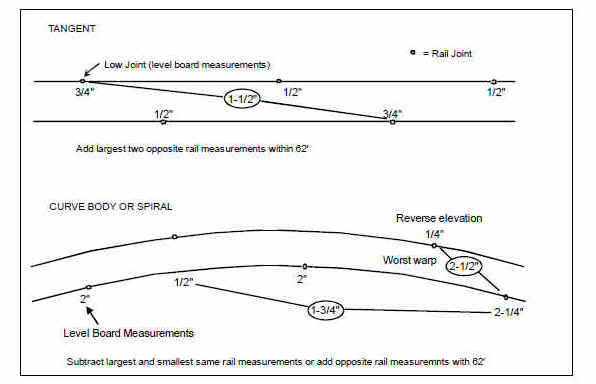
max (§ 213.57) may impose at a curve body where reverse elevation is encountered.The parameter for the difference in crosslevel between any two points less than 62 feet apart is commonly referred to as the "warp" parameter. This parameter provides maximum change in crosslevel between two points within specific distances along the track. The warp parameter is, perhaps, the most critical of the surface parameters. Excessive warp contributes to wheel climb derailments. The following illustrates warp measurements.
The threshold values for warp represent minimum safety standards and encompass the full range of rolling stock in present-day operating fleets. Inspectors should be aware that some rolling stock, because of certain design and/or demonstrated performance characteristics, may be subject to additional operating restrictions and/or more restrictive warp thresholds as determined by individual railroads. The limits for warp apply anywhere along the track, (curves, spirals, and tangent segments), except that the limits shown in footnote "*" of the table apply in the special case in spirals where physical conditions prevent the more restrictive limits in the general warp parameter.
The footnote designated by a "*" of table is an exception to the above warp requirement in spirals in those few situations where the railroad has made a prior engineering decision, due to physical restrictions, to design a shorter spiral that would be found in standard construction. When encountering a spiral that does not have a sufficient length to "runoff" elevation in accordance with the warp parameter, the inspector must determine if the "short spiral" is a result of a man made or other natural obstruction. In short spirals, the amount of warp is determined by measuring the "variation" in crosslevel between two points 31 feet apart.
Examples of "short spiral" situations include rock cuts, tunnels, station platforms, etc. The following figure illustrates the application of the "*" footnote.
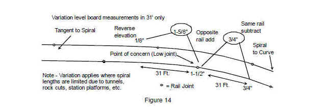
Railroads are expected to apply the variation parameter and thresholds only at locations where there is a clear history of restrictive physical characteristics.
When measuring track surface parameters remember the location of the transition points between tangent, spiral, and curve body are determined by actual physical layout and are not assumed to be synonymous with railroad markers, tags, curve charts, or similar information. Therefore, be governed accordingly when applying the "*" footnote or any other track geometry parameter.
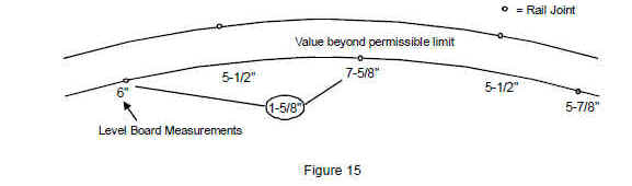
Under footnote 1 of the table, where the elevation at any point in a curve equals or exceeds 6 inches, the difference in crosslevel (warp) within 62 feet between that point and a point with greater elevation may not be more than 1½ inches regardless of track class. This footnote is included to address the condition where a vehicle is operating on a curve with a large amount of elevation and then encounters a warp condition. Since the vehicle is typically in an unbalanced condition, the warp may induce wheel climb. Slow speed curve negotiation is a particular concern since the wheels on the outside rail of the curve will tend to unload due to the overbalanced condition of the vehicle. Where this condition is found, the appropriate corrective action would be reduction to Class 1 speed under the provisions of § 213.9(b).
The following figure illustrates a warp exceeding 1½ inches at a curve with 6 inches of elevation.
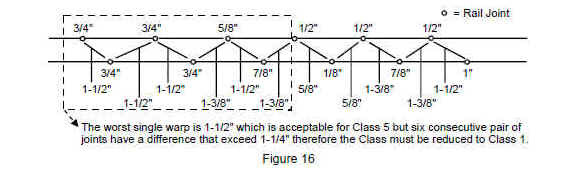
Footnote 2 of the table addresses the critical harmonic rock-off condition that may result in the vehicle rocking back and forth and derailing following wheel climb. It is considered rare that this condition could occur in CWR, but it may occur where "joint memory exists." In this case, while the condition is not a defect unless it exceeds the warp limits specified in the table, the inspector should call the condition to the attention of the railroad. The crosslevel difference (warp) may not exceed 1¼ inches on all six consecutive pairs of joints, under the conventional joint spacing (33-, 36-, 39-foot long rails). Each one of the six pairs must exceed 1¼ inches for this condition to be a defect. Additional joints that have been introduced outside of the regular joint spacing, characteristically as a result of rail repair, are not considered harmonic "joints" for the purposes of this footnote. The following figure illustrates a harmonic rock-off condition.
A condition with consecutive low-bolted joints may be in noncompliance with either the warp limits specified in the table or the requirements of footnote 2 of the § 213.63 table. Inspectors shall consider any contiguous group of joints as one defect and note the number of joints. If the harmonic condition continues beyond the seven joints, the inspector is not required to record another defect, but must note the number of consecutive joints that make up the harmonic condition.
Jointed rail stagger that is not identical from stagger to stagger, such as in a curve or when a rail slightly longer than the original construction is installed, shall be considered in the harmonic calculation. Additional joints introduced by the installation of short rails are ignored in evaluating a harmonic condition.
Construction consisting of 79- or 80-foot rails does not result in harmonic rock-off conditions since they occur outside of vehicle truck spacing. For 79- or 80-foot rails and staggered spacing less than 10 feet, this footnote is not applicable and inspectors shall review the condition for compliance with other track surface parameters.
Inspectors shall carefully apply the provisions of footnote 2 of the § 213.63(a) table. An acceptable remedial action is to raise and tamp one or two joints in the middle of the consecutive low joints. This will break up the harmonics.
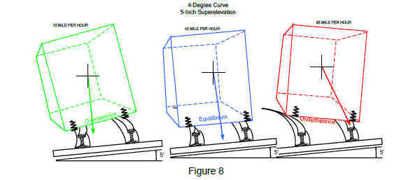
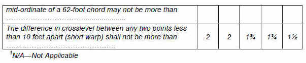
213.63(b) For operations at a qualified cant deficiency, Eu, of more than 5 inches, each track owner shall maintain the surface of the curve within the limits prescribed in the following table:
Guidance:
Paragraph 63(b) was introduced by the VTI final rule (78 F 16101, Mar. 13, 2013). The paragraph contains tighter, single-deviation geometry limits for operations above 5 inches of cant deficiency on curves. These limits include tighter 62-foot mid-chord offset (MCO) track surface and 31-foot MCO limits for track surface and 10-foot warp - the difference in crosslevel between any two points less than 10 feet apart. The other limits in rows 1 and 3 to 5 in paragraph 63(a) are still applicable.These limits provide an equivalent margin of safety for operations above 5 inches of cant deficiency. They are based on the results of simulation studies to determine the safe amplitudes of track geometry surface variations.
§213.65 Combined track alinement and surface deviations.
On any curved track where operations are conducted at a qualified cant deficiency, Eu, greater than 5 inches, the combination of alinement and surface deviations for the same chord length on the outside rail in the curve, as measured by a TGMS, shall comply with the following formula:
- Where—
- Am = measured alinement deviation from uniformity (outward is positive, inward is negative).
- AL = allowable alinement limit as per §213.55(b) (always positive) for the class of track.
- Sm = measured profile deviation from uniformity (down is positive, up is negative).
- SL = allowable profile limit as per §213.63(b) (always positive) for the class of track.
Guidance:
This section contains limits addressing combined track alinement and surface deviations for operations above 5 inches of cant deficiency on curves.The equation is given for computing the combined track alinement and surface deviations within a single chord length. The limits are intended to be used only with a TGMS, and applied on the outside rail in curves.
The Track Safety Standards have traditionally prescribed limits on geometry variations existing in isolation. However, a combination of track alinement and surface variations may result in undesirable vehicle response, even though neither the alinement nor the surface variation individually amounts to a deviation from the requirements in this part.
Section § 213.333(a)(1) contains TGMS inspection requirements for operations with cant deficiencies greater than 5 inches over Class 1 through 5 track. These requirements apply as required by § 213.57(i). Trains operating at high cant deficiencies increase the lateral wheel force exerted on the outside rail during curving, and hence decrease the margin of safety associated with the VTI safety limits in § 213.333. To address these concerns, simulation studies were performed to determine the safe amplitudes of combined track geometry variations. Results of this research showed that the equation-based safety limits in this section can provide a margin of safety for vehicle operations at any speeds and higher than 5 inch cant deficiencies.
- ARC-Tech.Net internet websites
- ww.railroadtraining.net
- PO Box 206, Kingsbury, IN 46345
- 512-553-6226
- Source Study Manual and Rules Book information provided by the Federal Railroad Administration.
- Presentation Copyright © 2007-2018ARC-Tech.Net. All rights reserved.