Subpart D – Track Structure
§ 213.101 Scope
This subpart prescribes minimum requirements for ballast, crossties, track assembly fittings, and the physical conditions of rails.
§ 213.103 Ballast; general
Unless it is otherwise structurally supported, all track shall be supported by material which will --
103(a) Transmit and distribute the load of the track and railroad rolling equipment to the subgrade;
103(b) Restrain the track laterally, longitudinally, and vertically under dynamic loads imposed by railroad rolling equipment and thermal stresses imposed by the rails;
Guidance: Ballast may consist of crushed slag, crushed stone, screened gravel, pit-run gravel, chat, cinders, scoria, pumice, sand, mine waste, or other native material, and is an integral part of the track structure. Ballast, regardless of the material, must satisfy the requirements stated in the TSS.
103(c) Provide adequate drainage for the track; and
103(d) Maintain proper track crosslevel, surface, and alinement.
Guidance:
Inspectors should consider the overall condition of a track when citing fouled ballast. Because ballast conditions can be subjective in nature, inspectors should also look to other indicators, such as a geometry condition. For example, a fouled ballast violation might be appropriate if the track has poor drainage and there is a geometry condition or a series of fouled ballast locations with geometry conditions.The term "geometry condition" used here and elsewhere in this manual means a track surface, gage, or alinement irregularity that does not exceed the allowable threshold for the designated track class. It exists due to the reduced or non-existent capability of one or more track structural components to hold the track to its preferred geometric position.
§ 213.109 Crossties
109(a) Crossties shall be made of a material to which rail can be securely fastened.
109(b) Each 39-foot segment of track shall have at a minimum-
(1) A sufficient number of crossties which in combination provide effective support that will -
- (i) Hold gage within the limits prescribed in §213.53(b);
- (ii) Maintain surface within the limits prescribed in §213.63; and
- (iii) Maintain alinement within the limits prescribed in §213.55.
(2) The minimum number and type of crossties specified in paragraph (b)(4) of this section and described in paragraph (c) or (d), as applicable, of this section effectively distributed to support the entire segment;
(3) At least one non-defective crosstie of the type specified in paragraphs (c) and (d) of this section that is located at a joint location as specified in paragraph (e) of this section; and
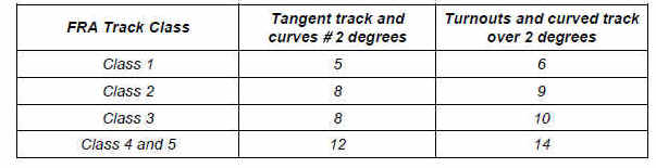
(4) The minimum number of crossties as indicated in the following table.
Guidance: The TSS determines the adequacy of crosstie support by including its functional requirements to maintain track geometry within the limits specified in Subpart C. The failure of the crossties to meet any of the three above criteria constitutes a deviation from the TSS.
Effective distribution has not been defined, but must not be interpreted by the inspector as synonymous with equally spaced. The language is intended to address situations where all of the nondefective or defective ties exist in a group at a short area of the 39-foot segment of track in question. Evidence that crossties are not effectively distributed includes, primarily, indications of an actual deviation or a geometry condition.
No criterion exists for the maximum distance between nondefective ties, and this measurement should not be used to describe a tie defect. If such a description is appropriate, it should be in terms of the number of consecutive defective ties in a group.
When citing 213 defect code 0109B2 (Crossties not effectively distributed to support a 39-foot segment of track), the inspector must show evidence of one or more of the geometry conditions cited in § 213.109(b)(1). Several factors may be documented if the defect is being cited. These factors include, but are not limited to:
• Geometry conditions.
• Class of track.
• Curvature.
• Traffic density (annual tonnage).
• Rail weight and condition.
• Condition of other components of the track.
When determining compliance with this section, the inspector must determine that crossties meet the requirements of effectiveness as defined above and make geometry measurements to verify that each 39-foot segment of track has:
• A sufficient number of effective ties to maintain geometry.
• The required number of nondefective ties for the track class as described in paragraph 213.109(b)(4).
• The proper placement of nondefective ties as described in paragraph 213.109(b)(4) and positioned as required in paragraph (e) to support joints.
The majority of crossties throughout the nation are made from wood. However, there are varieties of alternate designed crossties made from materials such as composites, steel, and concrete. These types of crossties are becoming more common throughout the industry. Because of the increased use of these alternate design crossties and their associated resilient type rails fasteners, inspectors should more rigorously consider the rail/crosstie interface. Also, see § 213.127, Rail fastenings.
109(c) Crossties, other than concrete, counted to satisfy the requirements set forth in paragraph (b)(4) of this section shall not be—
- (1) Broken through;
- (2) Split or otherwise impaired to the extent the crossties will allow the ballast to work through, or will not hold spikes or rail fasteners;
- (3) So deteriorated that the tie plate or base of rail can move laterally more than ½ inch relative to the crossties; or
- (4) Cut by the tie plate through more than 40 percent of a ties’ thickness.
Guidance:
Paragraph (c) mainly applies to wooden ties, although it does not explicitly exclude composite and steel ties.When a crosstie exhibits any one or more of the conditions described in the four criteria for evaluation [§ 213.109(c)1–4] it may be considered non-effective itself, although that determination may not always result in a defective condition that can be recorded under 213 Defect Codes 0109A, 0109B2, or 0109B3.
If track geometry measurements fail to meet the requirements of Subpart C, and there are an insufficient number of effective crossties, both geometry and crossties could be cited as defects. If geometry measurements exceed the allowable tolerance, but a determination cannot be made that crossties are the cause, it is appropriate to cite only the defective geometry.
FRA inspectors may use a PTLF described in § 213.110 for the purposes of measuring loaded gage to determine effective distribution of crossties. Refer to Appendix D–PTLF, instructions for non-GRMS territory under § 213.53.
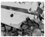
109(d) Concrete crossties counted to satisfy the requirements set forth in paragraph (b)(4) of this section shall not be--
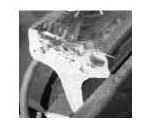
- (1) Broken through or deteriorated to the extent that prestressing material is visible;
- (2) Deteriorated or broken off in the vicinity of the shoulder or insert so that the fastener assembly can either pull out or move laterally more than ⅜ inch relative to the crosstie;
- (3) Deteriorated such that the base of either rail can move laterally more than ⅜ inch relative to the crosstie on curves of 2 degrees or greater; or can move laterally more than ½ inch relative to the crosstie on tangent track or curves of less than 2 degrees;
- (4) Deteriorated or abraded at any point under the rail seat to a depth of ½ inch or more;
- (5) Deteriorated such that the crosstie’s fastening or anchoring system, including rail anchors (see § 213.127(b)), is unable to maintain longitudinal rail restraint, or maintain rail hold down, or maintain gage due to insufficient fastener toeload; or
- (6) Configured with less than two fasteners on the same rail except as provided in § 213.127(c).
Guidance:
Crossties are evaluated individually by the definitional and functional criteria set forth in the regulations. Crosstie "effectiveness" is naturally subjective and requires good judgment in the application and interpretation of this standard. The soundness and durability of a crosstie is demonstrated when a 39-foot track segment maintains safe track geometry and structurally supports the imposed wheel loads with minimal deviation. Key to the track segment lateral, longitudinal, and vertical support is a strong track modulus, which is a measure of the vertical stiffness of the rail foundation. Continuous superior superstructure (including rails, crossties, fasteners, etc.) and high-quality ballast characteristics that transmit both dynamic and thermal loads to the subgrade are also important. Proper drainage that is free from the presence of excess moisture is an apparent and crucial factor in providing added structural support.Section 213.109 contains specific performance requirements for FRA Classes 1 through 5 track that address the unique characteristics of fastener reliability, concrete crossties, and roadbed stability. Inspectors should be aware of the three modes of concrete crosstie failure: support, stability, and electrical isolation. The compressive strength of concrete and the amount of prestress in its section composition provide the strength and stiffness necessary to support expected wheel loads. There is a balance between excessive stiffness that can lead to higher stresses at the bottom of the crosstie and at the rail seat.
Conversely, a loss of stiffness, caused by ever increasing axle loading, can lead to excessive rail deflections and damage to the ballast and subgrade. Inspectors should be aware that failure modes are not isolated to crosstie defects. Combinations of compliant but irregular track and rail geometry, poor drainage, insufficient ballast depth and subgrade soil conditions may contribute to failure or root causal factors.
Paragraph (d) delineates the requirements related to concrete crossties. Modern concrete crossties are designed to accept the stresses imposed by irregular rail head geometry and loss, excessive wheel loading caused by wheel irregularities (out of round), excessive unbalance speed, and track geometry defects. Section 213.109 considers the worst combinations of conditions, which can cause excessive impact and eccentric loading stresses that would increase failure rates and other measures concerning loss of toeload, longitudinal and lateral restraint, in addition to improper rail cant.
Paragraph (d) (1) states that as with non-concrete crossties, concrete crossties counted to fulfill the requirements of paragraph (b)(4) must not be broken through or deteriorated to the extent that prestressing material is visible.
Crossties must not be so deteriorated that the prestressing material has visibly separated from, or visibly lost bond with, the concrete, resulting either in the crosstie’s partial break-up, or in cracks that expose prestressing material due to spalls or chips, or in significant broken-out areas exposing prestressed material. Currently, metal reinforcing bars are used as the prestressing material in concrete crossties. FRA uses the term "prestressing material" in lieu of "metal reinforcing bars" to allow for future technological advances.
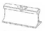
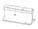
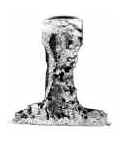
There is a distinction between the phrases "broken through" and "deteriorated to the extent that prestressing material is visible." Concrete crossties are manufactured in two basic designs: twin-block and mono-block. Twin-block crossties are designed with two sections of
concrete connected by exposed metal rods. A mono-block crosstie is similar in dimension to a timber or wood crosstie and contains prestress metal strands embedded into the concrete. The prestressing material in the concrete is observed at the ends of the crosstie for proper tension position. Prestressed reinforced concrete crossties are made by stressing the reinforcing material in a mold, then pouring cement concrete over the reinforcing material in the mold. After the concrete cures, the tension on the reinforcing material is released, and the ends of the reinforcing material are trimmed, if appropriate for the use. The prestressing material remains in tension against the concrete, which is very strong in compression. This allows the prestressed concrete to withstand both compressive and tensile loads. If the concrete spalls, or if the prestressing material is otherwise allowed to come out of contact with the concrete, then the prestressing material is no longer in tension. A concrete crosstie’s flexural strength and stiffness is lost when the prestress force is reduced through corrosion, concrete deterioration, or poor bond with the concrete due to improper manufacturing. The prestressing material may corrode if insufficient concrete cover or concrete cracking allows the intrusion of moisture and oxygen. When this happens, the once prestressed concrete crosstie can no longer withstand tensile loads, and it will fail very rapidly in service.Prestressing material is often exposed in a concrete crosstie as a crack, but it can also be exposed on the side of the tie. When prestressing material becomes exposed on the side of a crosstie, the prestressing material is no longer in tension, the prestressed concrete can no longer withstand the tensile loads, and therefore a concrete crosstie can structurally fail. This does not apply to reinforcing material left visible at the end of the crosstie during the manufacturing process.
The compressive strength of the concrete material and the amount of prestress applied in the manufacturing process provide the strength and stiffness necessary to adequately support and distribute wheel loads to the subgrade. The prestressing material encased in concrete hold the crosstie together and provides tensile strength. However, significant cracking or discernible deterioration exposure of the reinforcing strands to water and oxygen produces loss of the prestress force through corrosion, concrete deterioration, and poor bonding. Loss of the prestress force renders the crosstie susceptible to structural failure and as a consequence, stability failure relating to track geometry noncompliance.
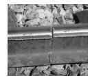
Crossties transversely broken between the rail seats and showing signs of further deterioration (loss of tension in prestressing material—upper and lower levels of exposure to metal strands) constitute failure. This means that there cannot be a complete separation of the concrete material making up the crosstie. Crossties must not be so deteriorated that the prestressing material has visibly separated from, or visibly lost bond with, the concrete, resulting either in the crosstie’s partial break-up, or in cracks that expose prestressing material due to spalls or chips, or in significant broken-out areas exposing prestressed material.
Crosstie failure is exhibited in three distinct ways: stress induced (breaks, cracks); mechanical (abrasion); or chemical decomposition. These conditions in small or large degrees compromise the crosstie’s ability to maintain proper gage, alignment, and track surface. Walking inspections would demonstrate clearly visible spalls, chips, cracks, and similar breaks. However, the compression of prestressed concrete crossties may close cracks as they occur, making them difficult to observe. Even such closed cracks probably weaken the crossties.
Breaks or cracks are divided into three general conditions: longitudinal cracks, center cracks, and rail seat cracks. Longitudinal cracks are horizontal through the crosstie and extend parallel to its length. They are initiated by high impacts on one or both sides of the rail bearing inserts. Crosstie center cracks are vertical cracks extending transversely (across) the crosstie. These cracks are unusual and are the result of high negative bending movement (usually center bound), originating at the crosstie top and extend to the bottom. Generally, the condition is progressive, and adjacent crossties may be affected. Rail seat cracks are vertical cracks that are not easily visible. They usually extend from the bottom of the crosstie on one or both sides of the crosstie and are often hard to detect. It is possible for a crosstie to be broken through, but, due to the location of the break, the prestressing material may not be visible. Crosstie strength, generally, does not fail unless the crack extends through the top layer of the prestressing material. Once the crack extends beyond the top layer, there is usually a loss of prestressing material and concrete bond strength.
Paragraph (d) (2) makes clear that crossties counted to fulfill the requirements of paragraph (b)(4) of this section must not be deteriorated or broken off in the vicinity of the shoulder or insert so that the fastener assembly can either pull out or move laterally more than three-eighths inch relative to the crosstie, as these conditions weaken rail fastener integrity.
Paragraph (d) (3) provides that a crosstie counted to fulfill the requirements of (b)(4) must not be deteriorated such that the base of either rail can move laterally more than three-eighths inch relative to the crosstie on curves of 2 degrees or greater; or can move laterally more than one-half inch relative to the crosstie on tangent track or curves of less than 2 degrees. This section allows for a combination rail movement, inward and outward, up to the dimensions specified, but not separately for each rail. The rail and fastener assembly work as a system capable of providing electrical insulation, adequate resistance to lateral displacement, undesired gage widening, rail canting, rail rollover, and abrasive or excessive compressive stresses. In accordance with policy and procedures, inspectors are encouraged to use the assigned portable track loading fixture (PTLF) in assessing the amount of lateral rail movement, wherever applicable.
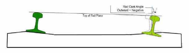
Paragraph (d) (4) requires that crossties counted to fulfill the requirements of paragraph (b)(4) of this section must not be deteriorated or abraded at any point under the rail seat to a depth of one-half inch or more. The measurement of one-half inch includes depth from the loss of rail pad material. The importance of having pad material in place with sufficient hysteresis (i.e., resilience (elasticity) to dampen high impact loading and recover) is paramount to control rail seat cracks caused by rail surface defects, wheel flats, or out of round wheels. Additionally, concrete crossties must be capable of providing adequate rail longitudinal restraint from excessive rail creepage or thermally induced forces or stress. "Rail creepage" is the tractive effort or pulling force exerted by a locomotive or car wheels, and "thermally induced forces or stress" is the longitudinal expansion and contraction of the rail, creating either compressive or tensile forces as the rail temperature increases or decreases, respectively. The loss of pad material causes a loss of toeload force, which may decrease longitudinal restraint. See the following figure. Note: inward or outward rail cant angle conventions are interchangeable among geometry measurement systems. FRA geometry cars record inward cant as positive, and outward cant as negative.
Paragraph (d) (5) requires that crossties counted to fulfill the requirements of paragraph (b)(4) of this section must not be deteriorated such that the crosstie’s fastening or anchoring system including rail anchors is unable to maintain longitudinal rail restraint, maintain rail hold down, or maintain gage, due to insufficient fastener toeload. Inspectors evaluate crossties individually by "definitional and functional" criteria. A compliant crosstie is demonstrated when a 39-foot track segment maintains safe track geometry and structurally supports the imposed wheel loads. In addition to ballast, anchors bear against the sides of crossties to control longitudinal rail movement, and certain types of fasteners also act to control rail movement by exerting a downward clamping force (toeload) on the upper rail base. Part of the complexity of crosstie assessment is the fastener component. Both crossties and fasteners act as a system to deliver the expected performance effect. A noncompliant crosstie and defective fastener assembly improperly maintains the rail position and support in the rail seat and contributes to excessive lateral gage widening (rail cant-rail rollover), and longitudinal rail movement because of loss of toeload.
Fastener assemblies or anchoring systems allow a certain amount of rail movement through the crosstie to effectively relieve rail creepage (tractive and thermal force build-up). However, because of the unrestrained buildup caused by rail creep, the longitudinal expansion and contraction of the rail creates either compressive or tensile forces, respectively. When longitudinal rail movement is ‘uncontrolled,’ it may disturb the track structure, causing misalignment (compression) or pull-apart (tensile) conditions to catastrophic failure. Specific longitudinal performance metrics would be undesirable and restrict certain fastener assembly designs and capabilities to control longitudinal rail movement. Therefore, inspectors must use good judgment in determining fastener assembly and crosstie effectiveness.
Paragraph (b)(6) makes clear that crossties counted to fulfill the requirements of paragraph (b)(4) of this section must not be configured with less than two fasteners on the same rail, except as provided in amended § 213.127(c), which includes requirements specific to fasteners used in conjunction with concrete crossties. As with nonconcrete ties, one of the safety requirements of an effective concrete tie is its ability to hold fasteners.
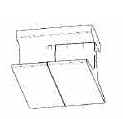
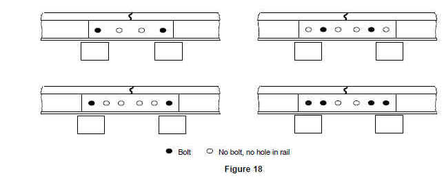
109(e) Class 1 and 2 track shall have one crosstie whose centerline is within 24 inches of each rail joint (end) location. Class 3, 4, and 5 track shall have either one crosstie whose centerline is within 18 inches of each rail joint location or two crossties whose centerlines are within 24 inches either side of each rail joint location. The relative position of these crossties is described in the following three diagrams:
(1) Each rail joint in Class 1 and 2 track shall be supported by at least one crosstie specified in paragraphs (c) and (d) of this section whose centerline is within 48 inches as shown in Figure 1.

(2) Each rail joint in Class 3, 4, and 5 track shall be supported by either at least one crosstie specified in paragraphs (c) and (d) of this section whose centerline is within 36 inches as shown in Figure 2, or:

(3) Two crossties, one on each side of the rail joint, whose centerlines are within 24 inches of the rail joint location as shown in Figure 3.

Guidance:
A nondefective joint tie must be found within the prescribed distance of the centerline of the joint measured at the rail end. In Classes 3 through 5, joint tie placement can be satisfied by either a one tie configuration, or by a two-tie configuration.For clarity of measurement and description:
1. Where a short piece of rail only inches in length is inserted between the rail ends and incorporated into the joint bar assembly, measure from the bar centerline. Also see § 213.121(d), Rail Joints.
2. Where nonsymmetrical bars exist, (e.g., five-hole heel block bars, five-hole compromise bars) measure from the design point where rail ends normally abut.
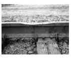
109(f) For track constructed without crossties, such as slab track, track connected directly to bridge structural components, track over servicing pits, etc., the track structure shall meet the requirements of paragraph (b)(1) of this section.
Guidance:
This paragraph addresses track constructed without crossties or bridge timbers, such as concrete-slab track, in which running rails are secured through fixation to another structural member.In general, discrepancies may arise in evaluation of crosstie conditions, if decisions are based only on an inspector’s maintenance experience, which varies widely among the inspectors. Inspectors should evaluate tie condition solely on the basis of the definitions provided in this section. Each crosstie must be evaluated individually by these criteria. As with all provisions of the TSS, the inspector must use judgment and discretion in the application of the crosstie standards. They should be used to describe conditions that constitute a risk to the safe operation of trains, and should not be applied in doubtful cases.
Gage rods are not an effective substitute for a proper crosstie and rail-fastening system. Gage rods can be subject to sudden failure, they provide no vertical rail support, and they provide no resistance to rail roll-over forces. However, gage rods may be installed when they are used as a secondary means of support for maintaining gage. Where gage rods are used and it is obvious that the condition of the crosstie and fastening system in the immediate vicinity is incapable of maintaining adequate gage, then the inspector should consider citing a crosstie or fastener defect.
Certain crossties may not be able to hold spikes or rail fasteners in their present condition. In these cases, it may be possible to bring the crossties into compliance by either plugging and re-spiking, or adding additional rail-holding or plate-holding spikes, or both.
Where conditions are closer to a rail-fastener issue (e.g., sound ties in track are not fastened to the rail), inspectors should refer to the guidance under § 213.127.
§ 213.110 Gage Restraint Measurement Systems
110(a) A track owner may elect to implement a Gage Restraint Measurement System (GRMS), supplemented by the use of a Portable Track Loading Fixture (PTLF), to determine compliance with the crosstie and fastener requirements specified in § 213.109 and § 213.127 provided that--
- (1) The track owner notifies the appropriate FRA Regional office at least 30 days prior to the designation of any line segment on which GRMS technology will be implemented; and
- (2) The track owner notifies the appropriate FRA Regional office at least 10 days prior to the removal of any line segment from GRMS designation.
Guidance: This paragraph provides for the implementation of a GRMS, supplemented by the use of a PTLF, to determine compliance with the crosstie and rail fastener requirements specified in §§ 213.109 and 213.127. Track owners electing to implement this technology must provide the appropriate FRA regional office with notification that specifically identifies the line segments where GRMS will be used. The appropriate FRA office is the headquarters location for the FRA region in which the GRMS designated line segment is located.Track and Rail and Infrastructure Integrity Compliance Manual Volume II, Chapter 1 – January 2014 2.1.61
The notification must be provided to FRA at least 30 days prior to the designation of any line segment which will be subject to the requirements of this section. Even though the notification requirement is satisfied, and the GRMS vehicle is determined to meet the minimum design requirements, the actual "triggering event," which places the line segment under the GRMS requirements, is the initial track survey with the GRMS vehicle.
Track owners must also provide FRA with at least 10 days notice prior to the removal of a line segment from GRMS designation. This requirement provides FRA with advance notice of the criteria change for the inspection of crossties and fasteners, and places some control over the random removal of line segments from GRMS designation.
110(b) Initial notification under paragraph (a)(1)of this section shall include--
- (1) Identification of the line segment(s) by timetable designation, milepost limits, class of track, or other identifying criteria; and
- (2) The most recent record of million gross tons of traffic per year over the identified segment(s).
Guidance:
This paragraph specifies what information track owners should include in their notifications to FRA about line segments designated for GRMS inspection. The information must include, at a minimum, the segment's timetable designation, milepost limits, track class, million gross tons of traffic per year, and any other identifying characteristics of the segment.For reasons of safety, GRMS vehicles have their split-axle in the retracted position when testing through special trackwork such as turnouts at grade rail-to-rail crossings (diamond), expansion joints, lift rail assemblies, etc. Where certain trackage within is not part of the designation, notifications should identify what and where these locations are and what distance approaching and leaving these locations are also excluded from GRMS designation. Locations excluded from GRMS designation will be subject to the requirements of §§ 213.109 and 213.127.
110(c) (1) The track owner shall also provide to FRA sufficient technical data to establish compliance with the following minimum design requirements of a GRMS vehicle:
(2) Gage restraint shall be measured between the heads of rail—
- (i) At an interval not exceeding 16 inches;
- (ii) Under an applied vertical load of no less than 10 kips per rail; and
- (iii) Under an applied lateral load that provides for a lateral/vertical load ratio of between 0.5 and 1.255, and a load severity greater than 3 kips but less than 8 kips per rail.
5GRMS equipment using load combinations developing L/V ratios that exceed 0.8 shall be operated with caution to protect against the risk of wheel climb by the test wheelset.
Guidance: This paragraph describes minimum design requirements for GRMS vehicles. Track owners must submit to FRA sufficient technical data so that the agency can establish whether the track owner is in compliance with these design requirements. This paragraph requires that gage must be measured between the heads of the rail at an interval not exceeding 16 inches. The paragraph provides for design flexibility by establishing acceptable ranges for the lateral/vertical load ratio and the resulting lateral load severity, both of which can
be satisfied by various load configurations, provided that the applied vertical load is not less than 10 kips per rail.
The rule provides for design flexibility by establishing acceptable ranges for various loading requirements. These ranges are considered absolute, and loading configurations that fall outside of the prescribed ranges will not be considered acceptable. Some loading configurations may develop high lateral/vertical load ratios and therefore lubrication of the gage face of the rail ahead of the split axle may be required to reduce the coefficient of friction to prevent wheel climb. Footnote 5 to this section cautions operations at L/V ratios exceeding 0.8 to protect against the risk of wheel climb by the test wheelset. This footnote is identical to footnote 10, which applies to § 213.333, Automated vehicle-based inspection systems, to ensure conformity between this section and its subpart G counterpart.
5 GRMS equipment using load combinations developing L/V ratios that exceed 0.8 shall be operated with caution to protect against the risk of wheel climb by the test wheelset.
110(d) Load severity is defined by the formula:
S = L−cV
Where—
S = Load severity, defined as the lateral load applied to the fastener system (kips).
L = Actual lateral load applied (kips).
c = Coefficient of friction between rail/tie, which is assigned a nominal value of 0.4.
V = Actual vertical load applied (kips), or static vertical wheel load if vertical load is not measured.
Guidance: This paragraph prescribes a formula for the calculation of "load severity" required by 110(c)(2) iii. The coefficient of friction at rail/tie interface can change the load severity level when the applied actual lateral and vertical loads are given. However, it is impractical to determine the actual coefficients of friction, which vary from place to place in the GRMS territory. A nominal value of 0.4 can always be used.
110(e) The measured gage values shall be converted to a Projected Loaded Gage 24 (PLG24) as follows—
PLG 24 = UTG + A × (LTG−UTG)
Where—
UTG = Unloaded track gage measured by the GRMS vehicle at a point no less than 10 feet from any lateral or vertical load application.
LTG = Loaded track gage measured by the GRMS vehicle at a point no more than 12 inches from the lateral load application point.
A = The extrapolation factor used to convert the measured loaded gage to expected loaded gage under a 24-kip lateral load and a 33-kip vertical load.
For all track—
Note: The A factor shall not exceed a value of 3.184 under any valid loading configuration.
L = Actual lateral load applied (kips).
V = Actual vertical load applied (kips), or static vertical wheel load if vertical load is not measured.
Guidance:
This paragraphs prescribes the formula for the calculation of the projected loaded gage 24 (PLG 24). The formula provides a method to normalize the PLG regardless actual lateral load loads applied by different GRMS systems. Accurate measurements of unloaded gage, GRMS loaded gage, and the lateral load applied are of critical importance because these measurements are used in the calculation of PLG 24 values which constitute a direct measure of track strength.To minimize the influence from adjacent loads, the unloaded track gage (UTG) must be measured by the GRMS vehicle at a point no less than 10 feet from any lateral or vertical load application and the loaded track gage (LPG) at a point no more than 12 inches from the lateral load application point.
110(f) The measured gage value shall be converted to a Gage Widening Ratio (GWR) as follows
![]()
Guidance:
This paragraph prescribes the formula for the calculation of the gage widening projection (GWP). The GWP is intended to compensate for the weight of the testing vehicle. Use of the GWP is supported by research results documented in the report titled "Development of Gage Widening Projection Parameter for the Deployable Gage Restraint Measurement System" (DOT/FRA/ORD-06/13, October 2006), which is available on FRA’s Web site.By making the criteria in this section consistent with those in § 213.333 in subpart G, the rule makes it easier for a track owner or railroad to comply with GRMS requirements regardless of the class of track.
110(g) The GRMS vehicle shall be capable of producing output reports that provide a trace, on a constant-distance scale, of all parameters specified in paragraph (l) of this section.
110(h) The GRMS vehicle shall be capable of providing an exception report containing a systematic listing of all exceptions, by magnitude and location, to all the parameters specified in paragraph (l) of this section.
110(i) The exception reports required by this section shall be provided to the appropriate person designated as fully qualified under §213.7 prior to the next inspection required under §213.233.
Guidance:
Paragraphs (g), (h), and (i) require that GRMS vehicles be capable of producing a stripchart of all the parameters specified in paragraph (l) of this section, as well as a printed exception report listing, by magnitude and location, all exceptions from these parameters. The exception report listing must be provided to the appropriate persons designated as fully qualified under § 213.7 prior to the next inspection required under § 213.233 of the TSS.Since the premise behind GRMS technology is to identify areas of weak gage restraint that either need immediate attention or must be continually monitored until the next GRMS inspection, the exception report listing must be retained and be available for review by the § 213.7 inspection personnel. FRA inspectors will obtain, or have access to, this exception report when conducting regular compliance inspections over GRMS designated line segments.
110(j) The track owner shall institute the necessary procedures for maintaining the integrity of the data collected by the GRMS and PTLF systems. At a minimum, the track owner shall–
- (1) Maintain and make available to the Federal Railroad Administration documented calibration procedures on each GRMS vehicle which, at a minimum, shall specify a daily instrument verification procedure that will ensure correlation between measurements made on the ground and those recorded by the instrumentation with respect to loaded and unloaded gage parameters; and
- (2) Maintain each PTLF used for determining compliance with the requirements of this section such that the 4,000-pound reading is accurate to within five percent of that reading.
- Guidance: This paragraph requires the track owner to institute procedures that will ensure the integrity of data collected by the GRMS and PTLF systems. Track owners must maintain documented calibration procedures on each GRMS vehicle and make them available upon request from an FRA representative. A daily instrument verification procedure is required to ensure that measurements of loaded and unloaded gage recorded by the instrumentation correlate to actual field measurements. Track owners must also develop and implement the necessary PTLF inspection and maintenance procedures so that the 4,000-pound reading is accurate within plus or minus 5 percent.
110(k) The track owner shall provide training in GRMS technology to all persons designated as fully qualified under §213.7 and whose territories are subject to the requirements of this section. The training program shall be made available to the Federal Railroad Administration upon request. At a minimum, the training program shall address--
- (1) Basic GRMS procedures;
- (2) Interpretation and handling of exception reports generated by the GRMS vehicle;
- (3) Locating and verifying defects in the field;
- (4) Remedial action requirements;
- (5) Use and calibration of the PTLF; and
- (6) Recordkeeping requirements.
Guidance:
This paragraph recognizes the need for persons designated as fully qualified under § 213.7, and whose territories are subject to the requirements of this section, to receive training on the implementation of GRMS technology. The track owner therefore is required to develop a formal GRMS training program that must be made available to FRA upon request. The training of affected employees is another "triggering event" that must be satisfied prior to a line segment being designated as GRMS territory under this section.The training program must provide detailed instruction on the specific areas identified in this paragraph. In particular, the training must address basic GRMS operational procedures, interpretation and handling of exception reports, how to locate and verify GRMS defects in the field, remedial action requirements to be initiated when defects are verified, how to use and calibrate the PTLF, and the recordkeeping requirements associated with the implementation of GRMS technology.
The requirement for GRMS training applies to fully qualified § 213.7 personnel under paragraphs (a) and (b) who are going to be subject to the requirements of this section. This is not to say that all fully qualified § 213.7 personnel need this training (e.g., welder foreman, production gang foreman, etc.). It is also not necessary for all fully qualified § 213.7 personnel who receive the GRMS training to be issued PTLFs. However, if circumstances arise where they need a PTLF, they should have access to one and be trained in how to use it and interpret the results.
The track owner must also take into consideration any relief personnel, newly qualified personnel, or personnel transferred from non-GRMS territory into a GRMS territory, which will be subject to the GRMS requirements. These personnel must be provided with sufficient instructions and training that enable them to demonstrate to the track owner that they know and understand the requirements of this section.
110(l) The GRMS record of lateral restraint shall identify two exception levels. At a minimum, the track owner shall initiate the required remedial action at each exception level as defined in the following table–
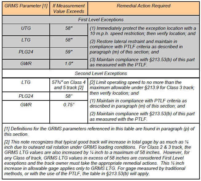
Guidance: The VTI final rule has corrected the table to renumber the remedial action specified for a second level exception. The remedial action has been designated as (1), (2), and (3) in the "Remedial action required" column, to be consistent with the remedial action specified for a first level exception. This paragraph specifies the parameters and threshold levels required to be reported as a record of lateral restraint following an inspection by a GRMS vehicle. The regulation requires that two levels of exceptions be reported during the GRMS inspection. Specific remedial actions are required for each level, as identified in the "Remedial action required" column. First level exceptions are required to be immediately protected by a 10 mph speed restriction until verification and corrective action can be instituted. Second level exceptions are to be monitored and maintained within the PTLF criteria outlined in paragraph (m) of this section.
The prior knowledge criteria is satisfied for those locations that are identified as first or second level exceptions on the record of lateral restraint which is generated following each GRMS inspection. Where field inspections conducted between GRMS inspections reveal an exception location that does not comply with either the track strength requirement or the gage requirement that are identified in paragraph (m) of this section, the inspector should consider recommending civil penalties. For locations that do not comply with the requirements of paragraph (m), and have not been identified on the record of lateral restraint as either a first or second level exception, the inspector shall exercise discretion to determine whether or not civil penalties should be recommended.
Footnote 2 in the table recognizes that typical good track will increase in total gage by as much as one-quarter inch due to outward rail rotation under GRMS loading conditions. Accordingly, for Class 2 and Class 3 track, the GRMS loaded track gage values are also increased by one-quarter inch to a maximum of 58 inches. GRMS loaded track gage values in excess of 58 inches must always be considered first level exceptions. This ¼-inch increase in gage applies only to GRMS loaded gage, and does not apply to PTLF gage measurements or to measurements made by more traditional methods.
110(m) Between GRMS inspections, the PTLF may be used as an additional analytical tool to assist fully qualified § 213.7 individuals in determining compliance with the crosstie and fastener requirements of § 213.109 and § 213.127. When the PTLF is used, whether as an additional analytical tool or to fulfill the requirements of paragraph (l), it shall be used subject to the following criteria–
(1) At any location along the track that the PTLF is applied, that location will be deemed in compliance with the crosstie and fastener requirements specified in § 213.109 and § 213.127 provided that–
(i) The total gage widening at that location does not exceed ⅝ inch when increasing the applied force from 0 to 4,000 pounds; and
(ii) The gage of the track under 4,000 pounds of applied force does not exceed the allowable gage prescribed in §213.53(b) for the class of track.
(2) Gage widening in excess of ⅝ inch shall constitute a deviation from Class 1 standards.
(3) A person designated as fully qualified under §213.7 retains the discretionary authority to prescribe additional remedial actions for those locations, which comply with the requirements of paragraph (m)(1)(i) and (ii) of this section.
(4) When a functional PTLF is not available to a fully qualified person designated under §213.7, the criteria for determining crosstie and fastener compliance shall be based solely on the requirements specified in §213.109 and §213.127.
(5) If the PTLF becomes non-functional or is missing, the track owner will replace or repair it before the next inspection required under §213.233.
(6) Where vertical loading of the track is necessary for contact with the lateral rail restraint components, a PTLF test will not be considered valid until contact with these components is restored under static loading conditions.
Guidance: While the remedial action table in paragraph (l) requires the use of the PTLF to measure compliance with the lateral restraint and gage requirements at identified exception locations in GRMS territory, paragraph (m) also provides for the use of a PTLF as an additional analytical tool by fully qualified § 213.7 individuals at other locations in GRMS territory. Paragraph (m) also describes the manner in which a PTLF must be used in GRMS territory, whether it is being used as an additional analytical tool or being used to meet the remedial action requirements set forth in paragraph (l). Compliance with §§ 213.109 and 213.127 will be demonstrated when a PTLF is applied and (1) the total gage widening at that location does not exceed five-eighths inch when increasing the applied force from 0 to 4,000 pounds; and (2) the gage of the track measured under 4,000 pounds of applied force does not exceed the allowable gage prescribed in § 213.53(b) of this section for the class of track involved. Gage widening in excess of five-eighths inch shall constitute a deviation from Class 1 standards.
At locations where compliance with the crosstie and rail fastener requirements have been demonstrated through the use of a PTLF, a fully qualified § 213.7 individual retains the discretionary authority to prescribe additional remedial actions, such as the placement of speed restrictions, if the individual deems it necessary. FRA inspectors will determine compliance with the crosstie and fastener requirements for gage restraint solely on the basis of the PTLF measurements.
Where crossties are found to be so severely split or plate-cut to the extent that they are incapable of providing adequate vertical support, and conditions have degraded to the point where track surface conditions are approaching the allowable limit for the class of track, inspectors shall continue to consider writing a defect. In such a case use 213 defect code 0109B2, "crossties not effectively distributed to support a 39-foot segment of track." Inspectors should record the track surface geometry condition as well as the contributing condition of the crossties in the description column.
When a functional PTLF is not available to a fully qualified § 213.7 individual during a scheduled inspection under § 213.233 of this part, the track owner must repair or replace the PTLF prior to the next inspection required under § 213.233, or crosstie and rail fastener compliance will be based solely on the requirements specified in §§ 213.109 and 213.127.
At locations where crosstie or rail fastening compliance is questioned and vertical loading of the track structure is necessary to restore contact with the lateral rail restraint components, the crossties must be raised until lateral restraint contact is restored and a PTLF measurement must then be made.
If the track owner fails to immediately restore contact between the rail and the fastening system so that a valid PTLF test can be performed, this non-action will in effect remove this location from the GRMS standard and the inspector will determine compliance based on §§ 213.109 and 213.127.
Likewise, where gage rods have been installed which preclude a valid PTLF test to determine gage restraint of crossties and fasteners, this action will in effect remove the location from the GRMS standard and the inspector will determine compliance based on §§ 213.109 and 213.127.
110(n) The track owner shall maintain a record of the two most recent GRMS inspections at locations which meet the requirements specified in §213.241(b). At a minimum, records shall indicate the following--
- (1) Location and nature of each First Level exception; and
- (2) Nature and date of remedial action, if any, for each exception identified in paragraph (n)(1) of this section.
Guidance:
This paragraph requires the track owner to maintain a record of the two most recent GRMS inspections at locations meeting the requirements specified in § 213.241(b). The records must indicate the location and nature of each First Level exception, and the nature and date of initiated remedial action, if any, for each First Level exception. First Level exceptions are described in the Remedial Action Table in paragraph (l).The record required under paragraph (n) is also the official record of lateral restraint and needs to identify both exception levels; however, the remedial action taken is required to be shown only for First Level exceptions. Records will be maintained at locations that meet the requirements specified in § 213.241(b).
110(o) The inspection interval for designated GRMS line segments shall be such that--
- (1) On line segments where the annual tonnage exceeds two million gross tons, or where the maximum operating speeds for passenger trains exceeds 30 m.p.h., GRMS inspections must be performed annually at an interval not to exceed 14 months; or
- (2) On line segments where the annual tonnage is two million gross tons or less and the maximum operating speed for passenger trains does not exceed 30 m.p.h., the interval between GRMS inspections must not exceed 24 months.
Guidance. Paragraph (o) details the GRMS inspection requirements which is illustrated in the following table:
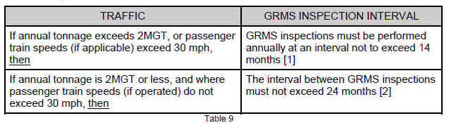
[1] The maximum interval of 14 months is intended to provide some flexibility for scheduling when it may not be possible to schedule annual inspections within the same calendar month each year.
[2] This extended frequency is an attempt to make the technology more accessible to short line operators who may not have the financial or equipment resources available to larger railroads. For example, a GRMS inspection may be scheduled at up to 24-month intervals if the railroad had 2 million annual tons or less and passenger trains were not authorized to operate at more than 30 mph.
110(p) As used in this section--
- (1) Gage Restraint Measurement System (GRMS) means a track loading vehicle meeting the minimum design requirements specified in this section.
- (2) Gage Widening Ratio (GWR) means the measured gage widening, which is the difference between loaded and unloaded gage, at the applied loads, projected to reference loads of 16 kips of lateral force and 33 kips of vertical force.
- (3) L/V ratio means the numerical ratio of lateral load applied at a point on the rail to the vertical load applied at that same point. GRMS design requirements specify an L/V ratio of between 0.5 and 1.25. GRMS vehicles using load combinations developing L/V ratios which exceed 0.8 must be operated with caution to protect against the risk of wheel climb by the test wheelset.
- (4) Load severity means the amount of lateral load applied to the fastener system after friction between rail and tie is overcome by any applied gage-widening lateral load.
- (5) Loaded Track Gage (LTG) means the gage measured by the GRMS vehicle at a point no more than 12 inches from the lateral load application point.
- (6) Portable Track Loading Fixture (PTLF) means a portable track loading device capable of applying an increasing lateral force from 0 to 4,000 pounds on the web/base fillet of each rail simultaneously.
- (7) Projected Loaded Gage (PLG) means an extrapolated value for loaded gage calculated from actual measured loads and deflections. PLG 24 means the extrapolated value for loaded gage under a 24,000 pound lateral load and a 33,000 pound vertical load.
- (8) Unloaded Track Gage (UTG) means the gage measured by the GRMS vehicle at a point no less than 10-feet from any lateral or vertical load.
- [66 FR 1899, Jan. 10, 2001; 66 FR 8372, Jan. 31, 2001, as amended at 78 FR 16102, Mar. 13, 2013]
Guidance. This paragraph prescribes a list of definitions of terms essential to the implementation of GRMS technology.
A well-documented pattern of repeated or widespread deviations from the requirements of this section by the track owner will effectively terminate the options afforded by this section. The affected track would then become subject to the requirements of § 213.109 and § 213.127.
§ 213.113 Defective rails
(a) When an owner of track to which this part applies learns, through inspection or otherwise, that a rail in that track contains any of the defects listed in the following table, a person designated under §213.7 shall determine whether or not the track may continue in use. If he determines that the track may continue in use, operation over the defective rail
is not permitted until -- (1) The rail is replaced; or (2) The remedial action prescribed in the table is initiated.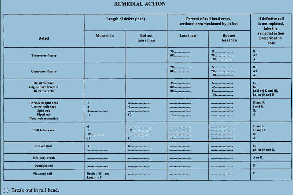
Notes:
A. Assign person designated under §213.7 to visually supervise each operation over defective rail.
A2. Assign person designated under §213.7 to make visual inspection. After a visual inspection, that person may authorize operation to continue without continuous visual supervision at a maximum of 10 m.p.h. for up to 24 hours prior to another such visual inspection or replacement or repair of the rail.
B. Limit operating speed over defective rail to that as authorized by a person designated under §213.7(a), who has at least one year of supervisory experience in railroad track maintenance. The operating speed cannot be over 30 m.p.h. or the maximum allowable speed under §213.9 for the class of track concerned, whichever is lower.
C. Apply joint bars bolted only through the outermost holes to defect within 20 days after it is determined to continue the track in use. In the case of Classes 3 through 5 track, limit operating speed over defective rail to 30 m.p.h. until joint bars are applied; thereafter, limit speed to 50 m.p.h. or the maximum allowable speed under §213.9 for the class of track concerned, whichever is lower. When a search for internal rail defects is conducted under §213.237, and defects are discovered in Classes 3 through 5 which require remedial action C, the operating speed shall be limited to 50 m.p.h., or the maximum allowable speed under §213.9 for the class of track concerned, whichever is lower, for a period not to exceed 4 days. If the defective rail has not been removed from the track or a permanent repair made within 4 days of the discovery, limit operating speed over the defective rail to 30 m.p.h. until joint bars are applied; thereafter, limit speed to 50 m.p.h. or the maximum allowable speed under §213.9 for the class of track concerned, whichever is lower.
D. Apply joint bars bolted only through the outermost holes to defect within 10 days after it is determined to continue the track in use. In the case of Classes 3 through 5 track, limit operating speed over the defective rail to 30 m.p.h. or less as authorized by a person designated under §213.7(a), who has at least one year of supervisory experience in railroad track maintenance, until joint bars are applied; thereafter, limit speed to 50 m.p.h. or the maximum allowable speed under §213.9 for the class of track concerned, whichever is lower.
E. Apply joint bars to defect and bolt in accordance with §213.121(d) and (e).
F. Inspect rail 90 days after it is determined to continue the track in use.
G. Inspect rail 30 days after it is determined to continue the track in use.
H. Limit operating speed over defective rail to 50 m.p.h. or the maximum allowable speed under §213.9 for the class of track concerned, whichever is lower.
I. Limit operating speed over defective rail to 30 m.p.h. or the maximum allowable speed under §213.9 for the class of track concerned, whichever is lower.
(b) As used in this section --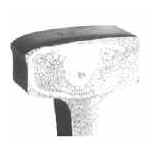
(1) Transverse fissure means a progressive crosswise fracture starting from a crystalline center or nucleus inside the head from which it spreads outward as a smooth, bright, or dark, round or oval surface substantially at a right angle to the length of the rail. The distinguishing features of a transverse fissure from other types of fractures or defects are the crystalline center or nucleus and the nearly smooth surface of the development which surrounds it.
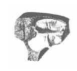
(2) Compound fissure means a progressive fracture originating in
a horizontal split head which turns up or down in the head of the rail as a
smooth, bright, or dark surface progressing until substantially at a right angle
to the length of the rail. Compound fissures require examination of both faces
of the fracture to locate the horizontal split head from which they originate.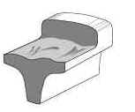
(3) Horizontal split head means a horizontal progressive defect originating inside of the rail head, usually ¼ inch or more below the running surface and progressing horizontally in all directions, and generally accompanied by a flat spot on the running surface. The defect appears as a crack lengthwise of the rail when it reaches the side of the rail head.
(4) Vertical split head means a vertical split through or near the middle of the head, and extending into or through it. A crack or rust streak may show under the head close to the web or pieces may be split off the side of the head.
(5) Split web means a lengthwise crack along the side of the web and extending into or through it.
(6) Piped rail means a vertical split in a rail, usually in the web, due to failure of the shrinkage cavity in the ingot to unite in rolling.
(7) Broken base means any break in the base of the rail.
(8) Detail fracture means a progressive fracture originating at or near the surface of the rail head. These fractures should not be confused with transverse fissures, compound fissures, or other defects which have internal origins. Detail fractures may arise from shelly spots, head checks, or flaking.
 (9) Engine burn fracture means a progressive fracture
originating in spots where driving wheels have slipped on top of the rail head.
In developing downward they frequently resemble the compound or even transverse
fissures with which they should not be confused or classified.
(9) Engine burn fracture means a progressive fracture
originating in spots where driving wheels have slipped on top of the rail head.
In developing downward they frequently resemble the compound or even transverse
fissures with which they should not be confused or classified.
 (10) Ordinary break means a partial or complete break in which
there is no sign of a fissure, and in which none of the other defects described
in this paragraph (b) are found.
(10) Ordinary break means a partial or complete break in which
there is no sign of a fissure, and in which none of the other defects described
in this paragraph (b) are found.
 (11) Damaged rail means any rail broken or injured by wrecks,
broken, flat, or unbalanced wheels, slipping, or similar causes.
(11) Damaged rail means any rail broken or injured by wrecks,
broken, flat, or unbalanced wheels, slipping, or similar causes.
 (12) Flattened rail means a short length of rail, not at a
joint, which has flattened
out across the width of the rail head to a depth of ⅜ inch or
more below the rest of the rail. Flattened rail occurrences have no repetitive
regularity and thus do not include corrugations, and have no apparent localized
cause such as a weld or engine burn. Their individual length is relatively
short, as compared to a condition such as head flow on the low rail of curves.
(12) Flattened rail means a short length of rail, not at a
joint, which has flattened
out across the width of the rail head to a depth of ⅜ inch or
more below the rest of the rail. Flattened rail occurrences have no repetitive
regularity and thus do not include corrugations, and have no apparent localized
cause such as a weld or engine burn. Their individual length is relatively
short, as compared to a condition such as head flow on the low rail of curves.
 (13) Bolt hole crack means a crack across the web, originating
from a bolt hole, and progressing on a path either inclined upward toward the
rail head or inclined downward toward the base. Fully developed bolt hole cracks
may continue horizontally along the head/web or base/web fillet, or they may
progress into and through the head or base to separate a piece of the rail end
from the rail. Multiple cracks occurring in one rail end are considered to be a
single defect. However, bolt hole cracks occurring in adjacent rail ends within
the same joint must be reported as separate defects.
(13) Bolt hole crack means a crack across the web, originating
from a bolt hole, and progressing on a path either inclined upward toward the
rail head or inclined downward toward the base. Fully developed bolt hole cracks
may continue horizontally along the head/web or base/web fillet, or they may
progress into and through the head or base to separate a piece of the rail end
from the rail. Multiple cracks occurring in one rail end are considered to be a
single defect. However, bolt hole cracks occurring in adjacent rail ends within
the same joint must be reported as separate defects.
 (14) Defective weld means a field or plant weld containing any
discontinuities or pockets, exceeding 5 percent of the rail head area
individually or 10 percent in the aggregate, oriented in or near the transverse
plane, due to incomplete penetration of the weld metal between the rail ends,
lack of fusion between weld and rail end metal, entrainment of slag or sand,
under-bead or other shrinkage cracking, or fatigue cracking. Weld defects may
originate in the rail head, web, or base, and in some cases, cracks may progress
from the defect into either or both adjoining rail ends.
(14) Defective weld means a field or plant weld containing any
discontinuities or pockets, exceeding 5 percent of the rail head area
individually or 10 percent in the aggregate, oriented in or near the transverse
plane, due to incomplete penetration of the weld metal between the rail ends,
lack of fusion between weld and rail end metal, entrainment of slag or sand,
under-bead or other shrinkage cracking, or fatigue cracking. Weld defects may
originate in the rail head, web, or base, and in some cases, cracks may progress
from the defect into either or both adjoining rail ends.
(15) Head and web separation means a progressive fracture, longitudinally separating the head from the web of the rail at the head fillet area.
Guidance: The remedial actions required for defective rails specify definite time limits and speeds. The remedial actions also allow certain discretion to the track owner for the continued operation over certain defects. Inspectors should consider all rail defects dangerous and care should be taken to determine that proper remedial actions have been accomplished by the railroad. When more than one defect is present in a rail, the defect requiring the most restrictive remedial action shall govern.
The remedial action table and specifications in the rule address the risks associated with rail failure. These risks are primarily dependent upon defect type and size and should not be dependent upon the manner or mechanism that reveals the existence of the defect. Failure of the track owner to comply with the operational (speed) restrictions, maintenance procedures and the prescribed inspection intervals specified in this section and § 213.237 (Defective rails and Inspection of rail, respectively), may constitute a violation of the TSS.
Note "A2" addresses mid-range transverse defect sizes. This remedial action allows for train operations to continue at a maximum of 10 mph up to 24 hours, following a visual inspection by a person designated under § 213.7. If the rail is not replaced, another 24-hour cycle begins.
Note "B" limits speed to that as authorized by a person designated under § 213.7(a) who has at least 1 year of supervisory experience in track maintenance. The qualified person has the responsibility to evaluate the rail defect and authorize the maximum operating speed over the defective rail based on the size of the defect and the operating conditions; however, the maximum speed over the rail may not exceed 30 mph or the maximum speed under § 213.9 for the class of track concerned, whichever is lower.
Notes "C," "D," and "H" limit the operating speed, following the application of joint bars, to 50 m.p.h. or the maximum allowable speed under § 213.9 for the class of track concerned, whichever is lower. When the maximum speed specified in notes "B," "C," "D," and "H" exceeds the current track speed, the railroad is required to record the defect. For example, when a railroad determines that remedial action "B" is required and the track speed already is 30 mph or less, the railroad must record the defect. This indicates that the railroad is aware of the characteristics of the defective rail and has designated a permissible speed in compliance with the regulation.
When an FRA inspector discovers a defective rail that requires the railroad representative to determine whether to continue the track in use and to designate the maximum speed over the rail, the inspector should inquire as to the representative's knowledge of the defect and remedial action. If the railroad was not aware of the defect prior to the FRA inspection, the FRA inspector should observe the actions taken by the railroad representative to determine compliance. If the railroad had previously found the defective rail, the FRA inspector should confirm the proper remedial action was taken. During records inspections, the FRA inspector should confirm that the defects were recorded and proper remedial actions were taken.
The remedial action table for defects failing in the transverse plane (transverse and compound fissures, detail and engine burn fractures, and defective welds) specifies a lower limit range base of 5 percent of the railhead cross-sectional area. If a transverse defect is reported to be less than 5 percent, the track owner is not legally bound to provide corrective action under the TSS. Defects reported less than 5 percent are not consistently found during rail breaking routines and therefore, defect determination within this range is not always reliable.
Transverse and compound fissure defects, weakened between 5 and 70 percent of cross-sectional head area require remedial action (note B). Defects in the range between 70 and less than 100 percent of cross-sectional head area require remedial action (note A2), as prescribed. Defects that affect 100 percent of the cross-sectional head area require remedial action (note A) as prescribed, the most restrictive. Inspectors should be aware that transverse and compound fissures are defects that fail in the transverse plane and are characteristic of rail that has not been control-cooled (normally rolled prior to 1936).
Defects identified and grouped as detail fracture, engine burn fracture, and defective welds, will weaken and also fail in the transverse plane. Detail fractures are characteristic of control-cooled rail [usually indicated by the letters CC or CH on the rail brand (i.e., 1360 RE CC CF&I 1982 1111). Their prescribed remedial action relates to a low range between 5 and 25 percent and a mid-range between 25 and 80 percent, for note (C) and note (D), respectively. Those defects require joint bar applications and operational speed restrictions within certain time frames. Defects extending less than 100 and more than 80 percent require a visual inspection. If the rail is not replaced, effectively repaired, or removed from service, an elective would be to restrict operation to a maximum of 10 mph for up to 24 hours, then perform another visual inspection.
The second sentence in remedial action note (C) addresses defects which are discovered in Classes 3 through 5 track during an internal rail inspection required under § 213.237, and which are determined not to be in excess of 25 percent of the rail head cross-sectional area. For these specific defects, a track owner may operate for a period not to exceed 4 days, at a speed limited to 50 mph or the maximum allowable speed under § 213.9 for the class of track concerned, whichever is lower. If the defective rail is not removed or a permanent repair is not made within 4 days of discovery, the speed is limited to 30 mph, until joint bars are applied or the rail is replaced.
The requirements specified in this second paragraph are intended to promote better utilization of rail inspection equipment and therefore maximize the opportunity to discover rail defects, which are approaching service failure size. The results of FRA’s research indicate that defects of this type and size range have a predictable slow growth life. Research further indicates that even on the most heavily utilized trackage in use today, defects of this type and size are unlikely to grow to service failure size in four days.
In the remedial action table, all longitudinal defects are combined within one group subject to identical remedial actions based on their reported size. These types of longitudinal defects all share similar growth rates and the same remedial actions are appropriate to each type.
Defective rails categorized as horizontal split head, vertical split head, split web, piped rail, and head-web separation, are longitudinal in nature. When any of this group of defects is more than 1 inch, but not more than 2 inches, the remedial action initiated, under note (H), is to limit train speed to 50 mph, and note (F) requires reinspecting the rail in 90 days, if deciding operations will continue. Defects in the range of more than 2 inches, but not more than 4 inches, require complying with notes (I) and (G), speed is limited to 30 mph and the rail reinspected in 30 days, if they decide operations will continue. When any of the five defect types exceed a length of 4 inches, under note (B) a person designated under § 213.7(a) who decides opertions will continue must authorize the operating speed, up to but not to exceed 30 mph, under note (B).
Another form of head-web separation, often referred to as a "fillet cracked rail," is the longitudinal growth of a crack in the fillet area, usually on the gage side of the outer rail of a curve. The crack may not extend the full width between the head and the web, but it is potentially dangerous. Evidence of fillet cracking is a hairline crack running beneath the head of rail with "bleeding" or rust discoloration. Fillet cracks often result from improper superelevation or from stress reversal as a result of transposing rail. The use of a mirror is an effective aid in examining rail and the determination of head-web cracks or separation in the body of the rail.
A "bolt hole crack" is a progressive fracture originating at a bolt hole and extending away from the hole, usually at an angle. They develop from high stress risers, usually initiating as a result of both dynamic and thermal responses of the joint bolt and points along the edge of the hole, under load. A major cause of this high stress is improper field drilling of the hole. Excessive longitudinal rail movement can also cause high stress along the edge of the hole.
When evaluating a rail end, which has multiple bolt hole cracks, inspectors will determine the required remedial action based on the length of the longest individual bolt hole crack.
Under note (H) and (F), the remedial action for a bolt hole crack, more than one-half inch, but not more than 1 inch, if the rail is not replaced, is to limit speed to 50 mph, or the maximum allowable under § 213.9 for the class of track concerned, whichever is lower, then reinspect the rail in 90 days, if operations will continue.
For bolt hole cracks greater than 1 inch, but not exceeding 1½ inches, notes (H) and (G) apply. These rails are required to be limited to 50 mph and reinspected within 30 days. For a bolt hole crack exceeding 1½ inches, a person qualified under § 213.7(a) may elect to designate a speed restriction, which cannot exceed 30 mph, or the maximum allowable under § 213.9 for the class of track concerned, whichever is lower.
Under notes (F) and (G), where corrective action requires rail to be reinspected within a specific number of days after discovery, several options for compliance may be exercised depending on the nature of the defect. For those defects, which are strictly internal and are not yet visible to the naked eye, the only option would be to perform another inspection with rail flaw detection equipment, either rail-mounted or hand-held. For defects that are visible to the naked eye and therefore measurable, a visual inspection or an inspection with rail flaw detection equipment are acceptable options. For certain defects enclosed within the joint bar area, such as bolt hole cracks and head-web separations, the joint bars must be removed if a visual reinspection is to be made.
The reinspection prescribed in notes (F) and (G) must be performed prior to the expiration of the 30 or 90 day interval. If the rail remains in track and is not replaced, the reinspection cycle starts over with each successive reinspection unless the reinspection reveals the rail defect to have increased in size and has therefore become subject to a more restrictive remedial action. This process continues indefinitely until the rail is removed from track.
Where corrective action requires rail to be reinspected within a specific number of days after discovery, the track owner may exercise several options for compliance. One option would be to perform another inspection with rail flaw detection equipment, either rail-mounted or hand-held. Another option would be to perform a visual inspection where the defect is visible and measurable. In the latter case, for certain defects enclosed within the joint bar area such as bolt hole breaks, removal of the joint bars will be necessary to comply with the reinspection requirement. If defects remain in track beyond the reinspection interval, the railroad must continue to monitor the defects and take the appropriate actions as required in the remedial action table.
A broken base can result from improper bearing of the base on a track spike or tie plate shoulder, and from over crimped anchors, or it may originate in a manufacturing flaw. With today’s higher axle loads, inspectors can anticipate broken base defects in 75-pound, and smaller, rail sections with an irregular track surface, especially on the field side. For any broken base discovered that is more than 1 inch, but less than 6 inches in length, the remedial action (note D) is to apply joint bars bolted through the outermost holes to defect within 10 days, if operations will continue. In Classes 3 through 5 track, the operating speed must be reduced to 30 mph or less, as authorized by a person under § 213.7(a), until joint bars are applied. After that, operating speed is limited to 50 mph or the maximum allowable under § 213.9 for the class of track concerned, whichever is lower.
Under note D, there are several acceptable "outermost hole" bolting arrangements for joint bars centered on a rail defect. See the following figure for an illustration of acceptable bolting arrangements. In all cases, railroads may not drill a bolt hole next to a defect that is being remediated with the application of joints bars (pursuant to note D). The reason for not drilling next to the defect is to prevent the propagation of the crack into the hole closest to the defect.
A broken base in excess of 6 inches requires the assignment of a person designated under § 213.7 to visually supervise each train operation over the defective rail. The railroad may apply joint bars to the defect and bolt them in accordance with §§ 213.121(d) and (e) and thereafter must limit train operations to 30 mph or the maximum allowable under § 213.9 for the class of track concerned, whichever is lower. As reference, the dimensions between the outermost holes of a 24-inch joint bar vary between approximately 15 and 18 inches and a 36-inch joint bar approaches 30 inches.
Inspectors should point out to the track owner that broken bases nearing these dimensions may negate the purpose for which the joint bars are applied. A broken base rail may be caused by damage from external sources, such as rail anchors being driven through the base by a derailed wheel. It is improper to consider them "damaged rail," as this defect is addressed by more stringent provisions applicable to broken base rails, under note (A) or (E) and (I).
Damaged rail can result from flat or broken wheels, incidental hammer blows, or derailed or dragging equipment. Reducing the operational speed in Classes 3 through 5 track to 30 mph until joint bars are applied, lessens the impact force imparted to the weaken area. Applying joint bars under note (D) ensures a proper horizontal and vertical rail end alinement in the event the rail fails.
Flattened rails (localized collapsed head rail) are also caused by mechanical interaction from repetitive wheel loadings. FRA and industry research indicate that these occurrences are more accurately categorized as rail surface conditions, not rail defects, as they do not, in themselves, cause service failure of the rail. Although it is not a condition shown to affect the structural integrity of the rail section, it can result in less than desirable dynamic vehicle responses in the higher speed ranges. The flattened rail condition is identified in the table, as well as in the definition portion of § 213.113(b), as being three-eighths inch or more in depth
below the rest of the railhead and 8 inches or more in length. As the defect becomes more severe by a reduced rail head depth, wheel forces increase.
The rule addresses flattened rail in terms of a specified remedial action for those of a certain depth and length. Those locations meeting the depth and length criteria shall be limited to an operating speed of 50 mph or the maximum allowable under § 213.9 for the class of track concerned, whichever is lower.
"Break out in rail head" is defined as a piece that has physically separated from the parent rail. Rail defects meeting this definition are required to have each operation over the defective rail visually supervised by a person designated under § 213.7. Inspectors need to be aware that this definition has applicability across a wide range of rail defects, as indicated in the Remedial Action Table. Where rail defects have not progressed to the point where they meet the definition of a break out, but due to the type, length and location of the defect, they present a hazard to continued train operation, inspectors should determine what remedial actions, if any, track owner should institute.
The following are two rail head break out examples where the "A" corrective action would be necessary:
Example One: There is a bolt hole break where the head of the rail is totally separated from the parent rail (either tight or loose), but that piece of rail will not physically lift out of the joint bars by hand. The inspector might determine that the separation was total by the fact that the separated piece rattled when tapped. It is important that railroads take the appropriate remedial action in this situation, because it is potentially very unsafe. It is impossible to know what will happen when the next train operates over this defect. That train could cause the piece to become so loose that it comes out of the place, cocks at an angle and causes a wheel to ramp up.
Example Two: A vertical split head defective rail where rail head separation is apparent because the inspector can determine that a physical separation has occurred through the rail head, but the rail head has not entirely separated over the entire length of the defect.
The issue of "excessive rail wear" continues to be evaluated by the Rail Integrity Task Force. The FRA believes that insufficient data exists at this time to indicate that parameters for this condition should be proposed as a minimum standard.
The Sperry Rail Service prints an excellent reference manual on rail defects. Inspectors are expected to be conversant with rail defect types, appearance, growth, hazards, and methods of detection.
Some railroads apply safety "weld straps" to thermite type field welds. These straps do not provide the same support of a joint bar. They would provide only limited support if a weld were to break under a train movement and as such, they do not comply with the provisions of corrective actions C, D, or E (installation of joint bars). Only a joint bar with full contact with the bottom of the rail head and rail base [see § 213.121 (a)] and with a manufactured relief for the weld material would comply with corrective actions C, D, or E.
When an FRA inspector finds a rail defect that appears to originate from fatigue at a bond wire attachment weld, the inspector should cite the railroad for 213 defect code 0113B.
Inspectors must also identify in their narrative the type of the rail defect (e.g., defective weld, detail fracture, etc.). FRA has added this defect code based on a National Transportation Safety Board (NTSB) recommendation arising from the NTSB investigation of a February 9, 2003, Canadian National Railway (CN) derailment in Tamaroa, Illinois. The NTSB determined that the probable cause of this accident was CN's placement of bond wire welds on the head of the rail just outside the joint bars, where untempered martensite associated with the welds led to fatigue cracking that, because of increased stresses associated with known soft ballast conditions, rapidly progressed to rail failure.

§ 213.115 Rail end mismatch
Any mismatch of rails at joints may not be more than that prescribed by the following table –
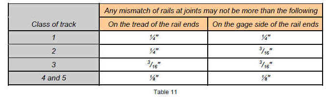
Guidance. Use a straightedge to determine the mismatch by holding the straightedge longitudinally along the higher rail (tread) or along the gage side (five-eighths inch down from the running surface) of the rail. Measure the distance directly between the straightedge and the rail. Disregard plastic overflow (gage side rail edge lipping), if any.
One example of mismatch occurs when a section of a rail is placed in the track where the existing rail head is gage- and/or treadworn. Mismatch can also occur when the joint bars are loose. However, if the loose bars do not result in mismatch exceeding the thresholds under this section, report the defect as loose joint bars (see § 213.121).
The standards prescribe both tread and gage mismatch thresholds. A mismatch may result in high impact forces especially at higher speeds. If a mismatch in excess of the allowable results in significant rail end damage, a violation should be considered.
Particular attention should be given to the mismatch on the gage side of a rail. A thin flange, skewed truck, or combination of both may cause a wheel to climb, particularly on the outer rail of a curve. Figure 18 shows the proper method to measure gage and tread mismatch.
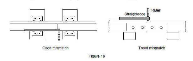
§ 213.118 Continuous welded rail (CWR); plan review and approval.
118(a) Each track owner with track constructed of CWR shall have in effect and comply with a plan that contains written procedures which address: the installation, adjustment, maintenance, and inspection of CWR; inspection of CWR joints; and a training program for the application of those procedures.
118(b) The track owner shall file its CWR plan with the FRA Associate Administrator for Railroad Safety/Chief Safety Officer (Associate Administrator). Within 30 days of receipt of the submission, FRA will review the plan for compliance with this subpart. FRA will approve, disapprove or conditionally approve the submitted plan, and will provide written notice of its determination.
118(c) The track owner’s existing plan shall remain in effect until the track owner’s new plan is approved or conditionally approved and is effective pursuant to paragraph (d) of this section.
118(d) The track owner shall, upon receipt of FRA’s approval or conditional approval, establish the plan’s effective date. The track owner shall advise in writing FRA and all affected employees of the effective date.
118(e) FRA, for cause stated, may, subsequent to plan approval or conditional approval, require revisions to the plan to bring the plan into conformity with this subpart. Notice of a revision requirement shall be made in writing and specify the basis of FRA’s requirement. The track owner may, within 30 days of the revision requirement, respond and provide written submissions in support of the original plan. FRA renders a final decision in writing. Not more than 30 days following any final decision requiring revisions to a CWR plan, the track owner shall amend the plan in accordance with FRA’s decision and resubmit the conforming plan. The conforming plan becomes effective upon its submission to FRA.
Guidance: All CWR plans must be submitted to FRA for review by the Track Division and then approval by the Associate Administrator for Railroad Safety/Chief Safety Officer. FRA reviews each plan for compliance with §§ 213.119(a) through (l). Regional track specialists may be requested to provide recommendations concerning the comprehensiveness of those procedures.
When conducting track inspections, an FRA inspector should have with him the most recent copy of a railroad’s CWR plan. This is important because it will enable the inspector to perform a proper inspection and determine compliance with the plan. Finalized CWR plans are posted on the FRA secured Web site for the inspector’s review and enforcement. If an inspector discovers substantial discrepancies between the official plan on file at FRA headquarters and the plan in the field (or that there are substantial discrepancies between the official plan on file with FRA and a railroad field manual), the inspector should notify the regional Track specialist.
FRA may also conditionally approve a plan. There might be instances where it would be beneficial for the agency to conditionally approve a plan. For example, FRA might decide that a plan should be approved, but might need to look into new technology proposed in the plan. FRA reserves the ability to later approve or disapprove a plan that it has formally conditionally approved.
A track owner may update or modify CWR procedures as necessary, but must resubmit any new or modified plan to FRA pursuant to § 213.118. Until the new plan is approved or conditionally approved and effective pursuant to paragraph (d), the track owner’s existing plan will remain in effect.
§ 213.119 Continuous welded rail (CWR); plan contents.
Guidance, General: In addition to safety-critical procedures listed in this section, the railroad may decide to include procedures based on administrative or economic considerations. For example, a railroad may choose to include instructions that limit the use of worn secondhand replacement rail because of an economic concern about the length of time that it might take to perform a satisfactory weld. The railroad may also include specific actions in their procedures that are to be taken when installation or maintenance work does not comply with its overall procedures.
Recording an activity that does not conform to the railroad’s CWR procedures does not provide the railroad with indefinite relief from responsibility for compliance when its procedures are not followed. Continued noncompliance may lead to an unsafe condition. The recordkeeping procedure is intended to provide a safety net by flagging those activities of noncompliance, which, if not brought into compliance in a timely manner, could lead to an unsafe condition. For example, CWR installed in the winter months without adequate rail anchors as prescribed by the written procedures and discovered in late summer would clearly be a deficient condition, regardless of if it was recorded. When in doubt as to what activities are considered safety related, the inspector should consult with the regional Track specialist.
Whenever conducting inspections on a railroad and that activity includes observation of CWR, FRA inspectors are to include only one “CWRP” unit on the header of their Railroad Inspection System for Personal Computers (RISPC) inspection report. Record one CWRP unit, regardless of the amount of CWR mileage inspected. Record the actual track mileage units using the activity codes MTH, MTW, etc. When a defect is taken for any aspect of § 213.119, FRA inspectors are to also designate CWRP for the line item “activity” cell. In addition, inspectors are to use CWRP in each line item activity cell when performing records inspections and recording deficiencies concerning CWR joint records.
The definition of a “buckling incident” explains the industry definition for such an event. However, the rule recognizes the importance of conditions that are precursors to buckles.
The two failure modes associated with track constructed with CWR are track buckles and pull-aparts. A track buckle is considered the more serious of the two and is characterized by the formation of a large lateral misalinement caused by:
• High compressive forces in the rail (thermal and mechanical loads).
• Weakened track conditions (weak track resistance, alinement deviations).
• Vehicle loads (a dynamic “wave” uplift and lateral vs. vertical ratios).
The track owner shall comply with the contents of the CWR plan approved or conditionally approved under § 213.118. The plan shall contain the following elements—
119(a) Procedures for the installation and adjustment of CWR which include—
- (1) Designation of a desired rail installation temperature range for the geographic area in which the CWR is located; and
- (2) De-stressing procedures/methods which address proper attainment of the desired rail installation temperature range when adjusting CWR.
Guidance: Track owners with track constructed of CWR are required to have in effect and comply with a CWR plan. This includes track owners who operate entirely on CWR track that has been designated as excepted track, pursuant to § 213.4. The procedures under § 213.119 do not apply to excepted track. (See § 213.5(b)). However, where a railroad designates a segment of track as excepted, it still must meet the requirements of at least Class 1 track for any portion of that track that is: (1) located within 30 feet of an adjacent track that is subjected to simultaneous use at speeds in excess of 10 mph, or (2) located on a bridge or on a public street or highway and there are trains with placarded cars. (See § 213.4(d).)
Railroads typically establish a desired rail installation temperature range for the geographical area that is higher than the annual mean temperature. This higher installation temperature will account for the expected reduction of the force-free temperature caused by track maintenance, train traffic, and other factors. As reference, the term for this expected occurrence is “rail neutral temperature shift.” A railroad’s failure to establish a designated installation temperature range for a specific territory is addressed under § 213.119(a).
- 119(b) Rail anchoring or fastening requirements that will provide sufficient restraint to limit longitudinal rail and crosstie movement to the extent practical, and specifically addressing CWR rail anchoring or fastening patterns on bridges, bridge approaches, and at other locations where possible longitudinal rail and crosstie movement associated with normally expected train-induced forces, is restricted.
- 119(c) CWR joint installation and maintenance procedures which require that—
- (1) Each rail shall be bolted with at least two bolts at each CWR joint;
Guidance: The track inspector should determine that any joints installed in CWR or connecting to CWR must have at least two bolts in each rail end, a minimum of four bolts installed in the joint bars, if not field welded at the time of installation. § 213.121(e).
This requirement serves as a reminder to track owners that they cannot create their own joint bolt requirements in their CWR plans that are less restrictive than those specified in the TSS.
(2) In the case of a bolted joint installed during CWR installation after October 21, 2009, the track owner shall either, within 60 days—
(i) Weld the joint;
(ii) Install a joint with six bolts; or
(iii) Anchor every tie 195 feet in both directions from the joint; and
Guidance: This section applies to major installations of CWR, such as more than 400 feet. It is not intended for plug rails. Note that the applicability date published in the final rule for this section (August 25, 2009) was corrected via the amendment published on October 21, 2009, at 74 FR 53889.
(3) In the case of a bolted joint in CWR experiencing service failure or a failed bar with a rail gap present, the track owner shall either—
Guidance: This section addresses CWR joints that experience a failure with a rail gap present. The definition for rail gap for this section is that the rail is under tension. An example of a joint failure under tension is a joint where the rail ends could not be pulled back together manually, as with the use of a drift pin, or if mechanical or thermal assistance is needed. A remedial action from § 213.119(c)(3) must be taken. Check for evidence of tension (such as bent and broken bolts) or application of thermal force (heat from repair rope, sawdust, or flammable mix).
(i) Weld the joint;
Guidance: The rail is welded at the time the joint is repaired.
(ii) Replace the broken bar(s), replace the broken bolts, adjust the anchors and, within 30 days, weld the joint;
Guidance: The 30-day time limit is only to allow the railroad adequate time to gather resources to weld the joint. If a CWR joint becomes battered before a repair can be completed and the track owner decides to cut in a plug rail to remove the battered joint, the track must immediately be brought into compliance as specified in § 213.121(e). The 30-day time limit starts from the original joint installation date for both joints. The remedial action 30-day period does not begin again when both CWR rail joints are required to be removed. If the joints have not been welded on the 31st day, a violation may be submitted to the track owner for failure to take the appropriate remedial action. The track owner must have selected the planned remedial action to be taken on the inspection report or other documentation that may be addressed in the CWR plan at the time the defect was discovered, and it must be documented. This written or electronic documentation must be made available upon request by FRA during regular business hours.
(iii) Replace the broken bar(s), replace the broken bolts, install one additional bolt per rail end, and adjust anchors;
(iv) Replace the broken bar(s), replace the broken bolts, and anchor every tie 195 feet in both directions from the CWR joint; or
(v) Replace the broken bar(s), replace the broken bolts, add rail with provisions for later adjustment pursuant to paragraph (d)(2) of this section, and reapply the anchors.
Guidance: The track owner should ensure that any rail added during the repair of a CWR pull-apart is properly adjusted back to the required safe neutral temperature in accordance with the railroad’s CWR plan. As the rail temperature rises, the expansion of rail increases. The track owner must have provisions in the CWR plan to slow order the affected track and make repairs and adjustment to bring the track into compliance. For example, in many cases, the addition of 1 inch of rail in a 1,000-foot string of CWR will lower its rail neutral temperature by 13 degrees.
If the remedial actions, described in §§ 213.119(c)(iii), (iv), or (v); are used and the affected joint fails again (with a rail gap present after the initial repair), additional, more restrictive repairs are required. This shows that the rail tension was not adequately addressed during the initial remedial action. CWR joints must be inspected for compliance with additional parts of the TSS, such as tie condition, surface, rail end mismatch, and properly fitting joint bars.
119(d) Procedures which specifically address maintaining a desired rail installation temperature range when cutting CWR including rail repairs, in-track welding, and in conjunction with adjustments made in the area of tight track, a track buckle, or a pull-apart. Rail repair practices shall take into consideration existing rail temperature so that—
(1) When rail is removed, the length installed shall be determined by taking into consideration the existing rail temperature and the desired rail installation temperature range; and
(2) Under no circumstances should rail be added when the rail temperature is below that designated by paragraph (a)(1) of this section, without provisions for later adjustment.
119(e) Procedures which address the monitoring of CWR in curved track for inward shifts of alinement toward the center of the curve as a result of disturbed track.
Guidance: Thermal and mechanical loads affecting track structure are decreased by the track owner’s adherence to the track engineering standards. Adherence to the track owner’s standards and the CWR plan promote CWR track stability and safety. Three engineering elements resist mechanical loads and thermal loads: lateral resistance, longitudinal resistance, and rail neutral temperature. Track buckles can be expected to occur predominately in the lateral dimension. Lateral resistance is critical to being dependent upon weight and size of crosstie material, ballast material type, shoulder width, crib content, and its level of consolidation. As degree of curvature increases, the buckling resistance decreases. A crosstie’s base, side (crib) friction, and ballast shoulder resistance contribute to the overall lateral resistance sustained. In general, each contributes (base 50 percent, side 20–30 percent, and shoulder 20–30 percent) to this resistance, but the ratios can vary depending on ballast condition. Lateral resistance varies in location depending on the ballast shoulder geometry, crosstie size and type, and state of ballast consolidation.
Thermal loads, by themselves, can cause a buckle and are often called “static buckling.” However, most buckling occurs under a combination of thermal and vehicle loads, termed “dynamic buckling.” Inspectors should place emphasis on vehicle (dynamic) effects on track lateral stability, where high rail temperatures and vehicle loading could progressively weaken the track due to dynamic uplift (flexural waves) and a buckle mechanism response induced by misalignment “growth.”
Because the majority of buckles occur under dynamic train movements, loading is an important element in the buckling mechanism. Elements of track lateral instability include:
• Formation of initial track misalinement caused by reduced local resistance.
• High impact loads, initial rail surface (weld) imperfections, “soft” spots in ballast, and curve (radial breathing) shifting.
• Misalinement growth caused by high lateral loads, increased longitudinal forces, track uplifts due to vertical loads, and train-induced vibration.
Inspectors may consider the above elements, combined with related evidence of actual defects, geometry conditions, or other defective structural conditions, when evaluating the adequacy of a railroad’s CWR stability procedures under §§ 213.119(b), (c), (d), and (e). Locations where track buckling are more likely to occur include: horizontal and vertical curves, bottom of grades, bridge approaches, highway-rail grade crossings, recently-disturbed track, and areas of heavy train starting or braking.
The signs or precursors of buckles include:
• Newly formed alinement deviations: wavy, kinky, snaky, etc.
• Rails rotating or lifting out of the tie plates and intermittent loose tie plates.
• Excessive “running” rail causing ties to plow or churn the ballast.
• Insufficient anchors and anchors not installed tightly against the tie.
• Insufficient ballast section in the crib and shoulder areas.
• Gaps at crosstie ends, especially on the low (inner) rail.
Curves are more prone to buckling because of the curvature effect, alinement imperfection sensitivity, and train loads. It is important for inspectors to consider when and where a buckle may occur (e.g., on track segments where the CWR installation occurred below the desired rail installation temperature range and there was inadequate control of the laying temperature or inadequate adjustment of the rail afterwards). In addition, inspectors should observe areas of recent maintenance involving either the ballast or rail, where there was inadequate reconsolidating time for a disturbed ballast or inadequate temperature adjustment when replacing a defective rail. As curvature increases, the buckling resistance decreases. Under some conditions, high degree curvature can undergo gradual lateral shift (progressive buckling). Lateral alinement deviations reduce the track buckling strength and can initiate growth to critical levels. Vertical alinement deviations can also influence buckling.
Lateral misalinement is an important consideration because it reduces the ability of the track to resist buckling. An alinement offset or mid-ordinate within allowable limits may “escalate” under the imposed loads. This is called “track shift.” A longitudinal force in curved track will cause CWR rail to move radically. Compressive loads in the rail during the summer tend to move the track outwards, and tensile loads in the winter will pull the track inward, a term known as “radial breathing.” Inspectors should review the allowable limits, under § 213.55, and evaluate the relevant alinement and track strength (§ 213.13, Movement under load) due to repeated thermal and vehicle loadings.
Generally speaking, a decrease in the rail neutral temperature of 30–40 degrees from the installation temperature can be critical and lead directly to buckling. Inspectors should monitor the following factors that may influence shifts in the force-free temperature: improper rail installation, inadequate rail anchors or fastenings, lateral movements in curves through lining operations, “skeletonized” track segments (ballast removed for maintenance purposes), and inadequate ballast section. Lateral and longitudinal restraint is influenced by the factors mentioned above and, if improperly maintained or allowed to exist in a defective state, it increases the opportunity for a track buckle.
Track buckles occur less frequently in tangent track than in curves. However, buckling in tangent track will generally occur suddenly and with more severe consequences.
The second of the two failure modes that can be associated with track constructed with CWR is a pull-apart. A rail’s decrease in temperature in the winter will create tensile forces. The maximum tensile load in the rail is determined by the difference in the installation or force-free temperature and the lowest rail temperatures. Enough tensile force can cause direct fracture at rail cross-sections with prior cracks, weak welds, or sheared joint bolts at CWR string end locations.
119(f) Procedures which govern train speed on CWR track when—
(1) Maintenance work, track rehabilitation, track construction, or any other event occurs which disturbs the roadbed or ballast section and reduces the lateral or longitudinal resistance of the track; and
(2) The difference between the average rail temperature and the average rail neutral temperature is in a range that causes buckling-prone conditions to be present at a specific location; and
Guidance: This requires that the railroad needs to record the new rail neutral temperature when performing rail repair and installation.
(3) In formulating the procedures under paragraphs (f)(1) and (f)(2) of this section, the track owner shall—
(i) Determine the speed required, and the duration and subsequent removal of any speed restriction based on the restoration of the ballast, along with sufficient ballast re-consolidation to stabilize the track to a level that can accommodate expected train-induced forces. Ballast re-consolidation can be achieved through either the passage of train tonnage or mechanical stabilization procedures, or both; and
(ii) Take into consideration the type of crossties used.
119(g) Procedures which prescribe when physical track inspections are to be performed.
(1) At a minimum, these procedures shall address inspecting track to identify—
(i) Buckling-prone conditions in CWR track, including—
(A) Locations where tight or kinky rail conditions are likely to occur; and
(B) Locations where track work of the nature described in paragraph (f)(1)(i) of this section has recently been performed; and
(ii) Pull-apart prone conditions in CWR track, including locations where pull-apart or stripped-joint rail conditions are likely to occur; and
(2) In formulating the procedures under paragraph (g)(1) of this section, the track owner shall—
(i) Specify when the inspections will be conducted; and
(ii) Specify the appropriate remedial actions to be taken when either buckling-prone or pull-apart prone conditions are found.
119(h) Procedures which prescribe the scheduling and conduct of inspections to detect cracks and other indications of potential failures in CWR joints. In formulating the procedures under this paragraph, the track owner shall—
Guidance: This paragraph requires each track owner to include in its CWR plan provisions for the scheduling and conducting of joint inspections. A person who is qualified under § 213.7(c) will perform the inspections required by this paragraph on foot at the joint.
(1) Address the inspection of joints and the track structure at joints, including, at a minimum, periodic on-foot inspections.
Guidance: This paragraph governs on-foot periodic inspections of CWR joints. Track owners are required to establish procedures for conducting these inspections. Upon identifying actual conditions of joint failures (i.e., broken or cracked joints bars) or potential conditions of joint failure, track owners must initiate the appropriate corrective action and keep the appropriate records. See § 213.119(h)(h)(5) and § 213.119(h)(7). In addition, when a track owner discovers CWR joints that are not in compliance with the requirements of the TSS, the track owner must take the appropriate remedial action required by Part 213. Inspectors should note that nothing in this paragraph interferes with the track owners’ continuing obligation to conduct track inspections under § 213.233. In addition, on-foot periodic inspections can be performed concurrently with § 213.233.
Periodic inspections, as referenced herein, are on-foot inspections of CWR joints that track owners must conduct on a regular basis. Track owners are required to conduct on-foot periodic inspections at the minimum intervals specified in paragraph (h)(6). Track owners, of course, are free to conduct these inspections more frequently than required.
(2) Identify joint bars with visible or otherwise detectable cracks and conduct remedial action pursuant to § 213.121;
Guidance: This paragraph requires track owners to identify joint bars with visible or otherwise detectable cracks and conduct remedial action pursuant to § 213.121. Railroad inspectors must know to distinguish between joint bars that are already cracked and joint bars that have the potential of cracking in the future. When a track owner discovers a cracked joint bar, the owner must take any remedial action specified in § 213.121; however, if the owner discovers a joint bar with actual or potential joint failure, the owner must take the corrective action specified by the CWR plan. Corrective action will be further addressed in paragraph (h)(5).
(3) Specify the conditions of actual or potential joint failure for which personnel must inspect, including, at a minimum, the following items:
(i) Loose, bent, or missing joint bolts;
(ii) Rail end batter or mismatch that contributes to instability of the joint; and
(iii) Evidence of excessive longitudinal rail movement in or near the joint, including, but not limited to; wide rail gap, defective joint bolts, disturbed ballast, surface deviations, gap between tie plates and rail, or displaced rail anchors;
Guidance: This paragraph identifies those items relating to joint inspections that track owners must address in their CWR plans. Inspectors should note that these items are the minimum that track owners should address. Of course, track owners are free to include additional items in their respective CWR plans. Railroad track inspectors are to identify and record action items listed during their inspection of joints because these items are related to the integrity of the joint, and thus, to the safety of trains that operate over these joints.
Inspectors should note that this list is not all-inclusive. There are other conditions that could indicate failure, and inspectors should urge track owners to consider all conditions, not just these listed examples.
(4) Specify the procedures for the inspection of CWR joints that are imbedded in highway-rail crossings or in other structures that prevent a complete inspection of the joint, including procedures for the removal from the joint of loose material or other temporary material;
Guidance: This paragraph requires track owners to include procedures in their CWR plans for the inspection of CWR joints that are imbedded in highway-rail grade crossings or in other structures that prevent a complete inspection of the joint (e.g., pans in fueling facilities, scales, passenger walkways at stations that cover the track, etc.). The plans must also include procedures for the removal of loose material or other temporary material from the joint.
With respect to the procedures for “imbedded” joints, inspectors should not expect railroads to disassemble or remove the track structure (e.g., remove pavement or crossing pads) to conduct an inspection of CWR joints. However, FRA expects that railroads will make every effort, to the extent practicable, to inspect the joints in these structures.
Inspectors need to be aware that CWR joints may sometimes be temporarily buried during maintenance (e.g., where ballast is distributed in the middle of the track and along the track) and therefore unavailable for inspection. FRA expects that railroads will take necessary measures to conduct inspections of these CWR joints and expects that railroads will schedule their maintenance to allow for a complete inspection of these joints. Where CWR joints are buried (e.g., by ballast), inspectors should understand that railroad maintenance personnel will wait for the completion of the track surfacing and dressing of the ballast before conducting their joint bar inspections. However, railroad employees may use hand tools or mechanical means to remove ballast from the sides of track joints, so that they can conduct an inspection of those track joints.
Finally, FRA notes that components of the track (such as crossties, fasteners, tie plates, etc.) are also not fully visible in highway-rail grade crossings and similar structures. Inspectors should note that FRA has never specifically exempted these items from the inspections required under Part 213. Inspectors should continue to expect that the railroads will inspect these areas to the maximum extent possible.
(5) Specify the appropriate corrective actions to be taken when personnel find conditions of actual or potential joint failure, including on-foot follow-up inspections to monitor conditions of potential joint failure in any period prior to completion of repairs;
Guidance: This paragraph requires track owners to specify in their plans the appropriate corrective actions that must be taken when track inspectors find conditions of actual or potential joint failure. Inspectors should note the difference between the terms “remedial actions” and “corrective action” and apply accordingly. Remedial actions are those actions which track owners are required to take as a result of requirements of Part 213 to address a noncompliant condition. For example, if a track owner discovers a cracked joint bar, the owner must replace it. See § 213.121 or the parallel requirement in the railroad’s CWR plan. Corrective actions, on the other hand, are those actions that track owners specify in their CWR plans to address conditions of potential joint failure, including, as applicable, repair, restrictions on operations, and/or additional on-foot inspection. To ensure clarity, FRA has defined these terms in § 213.119(j).
On-foot followup inspections, as referenced herein, are joint-specific and conducted in response to conditions that a track owner discovers during periodic inspections. Track owners will identify in their CWR plans the conditions that trigger followup inspections. For example, where a track owner identifies “replace bolt or inspect weekly” as a corrective action for a bent bolt, if a track inspector discovers a bent bolt during a periodic inspection and does not immediately replace it, then the track inspector will have to conduct followup inspections at that joint at the specified frequency (in this case, weekly).
(6) Specify the timing of periodic inspections, which shall be based on the configuration and condition of the joint:
Guidance: This paragraph requires railroad owners to specify the timing of on-foot periodic inspections. The minimum number of required joint inspections is addressed in the table in paragraph (h)(6)(i). The timing periods in this paragraph represent the minimum of what is expected. Railroad owners are encouraged to implement additional inspection periods as they determine necessary.
In paragraphs (h)(6)(ii) through (iv), inspectors should be aware that FRA is allowing exceptions to the minimum inspection frequencies for unscheduled detours, certain passenger trains, and items that are already inspected on a monthly basis pursuant to § 213.235. Each of these exceptions will be discussed in more detail below.
(i) Except as provided in paragraphs (h)(6)(ii) through (h)(6)(iv) of this section, track owners must specify that all CWR joints are inspected, at a minimum, in accordance with the intervals identified in the following table:
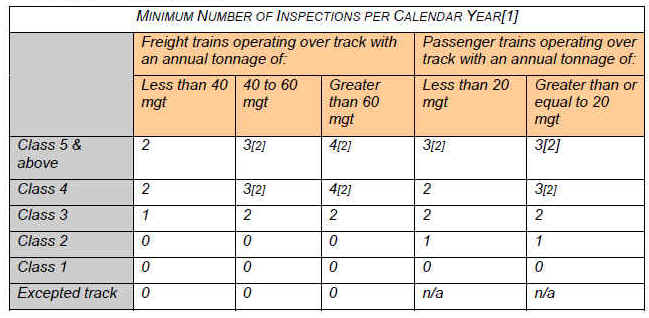
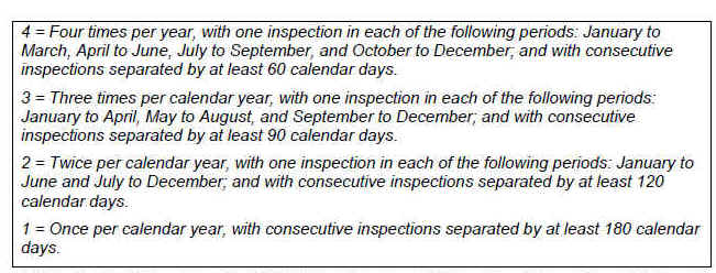
[1] Where a track owner operates both freight and passenger trains over a given segment of track, and there are two different possible inspection interval requirements, the more frequent inspection interval applies.
[2] When extreme weather conditions prevent a track owner from conducting an inspection of a particular territory within the required interval, the track owner may extend the interval by up to 30 calendar days from the last day that the extreme weather condition prevented the required inspection
Guidance: The first footnote provides that where a track owner operates both freight and passenger trains over a given segment of track, and there are two different possible inspection interval requirements, the more frequent inspection interval applies. This footnote was developed to address concerns over track shared by freight and passenger trains. It was anticipated that there could be a potential conflict with the inspection frequency required for the track if the track owner were to follow the chart for both types of trains. By requiring the more frequent inspections in situations of conflict, this footnote ensures greater safety and protection to track used for mixed purposes.
The second footnote was added in response to concerns regarding sensitivity of extreme regional weather conditions. Concern was raised with regard to the difficulty of inspecting CWR joints in northern regions when there is a large amount of snow. FRA notes that there could be times when it would be extremely difficult for a track owner to clear snow and ice from the joint in order for it to be seen for inspection. This footnote allows some flexibility for track owners in such a situation.
(ii) Consistent with any limitations applied by the track owner, a passenger train conducting an unscheduled detour operation may proceed over track not normally used for passenger operations at a speed not to exceed the maximum authorized speed otherwise allowed, even though CWR joints have not been inspected in accordance with the frequency identified in paragraph (h)(6)(i) of this section, provided that:
(A) All CWR joints have been inspected consistent with requirements for freight service; and
(B) The unscheduled detour operation lasts no more than 14 consecutive calendar days. In order to continue operations beyond the 14-day period, the track owner must inspect the CWR joints in accordance with the requirements of paragraph (h)(6)(i) of this section.
Guidance: This paragraph allows track owners, for a limited period of time, to operate passenger trains without lowering the track speed and without adhering to the required inspection frequencies for passenger trains pursuant to the table in § 213.119(h)(6)(i). This provision accommodates for unplanned outages, derailments, accidents, and other emergency situations. Track owners are still required to adhere to the applicable freight inspection frequencies. This provision is intended to provide relief to railroads that operate passenger trains and that have a last-minute emergency situation. However, if a track owner operates passenger trains at the normal track speed for more than 14 days, the track must be inspected at the appropriate passenger train levels, as detailed in the chart at § 213.119(h)(6)(i).
(iii) Tourist, scenic, historic, or excursion operations, if limited to the maximum authorized speed for passenger trains over the next lower class of track, need not be considered in determining the frequency of inspections under paragraph (h)(6)(i) of this section.
Guidance: As defined in § 213.119(l), tourist, scenic, historic, or excursion operations are railroad operations that carry passengers with the conveyance of the passengers to a particular destination not being the principal purpose. These operations run less frequently than intercity or commuter passenger trains, and occur most often on shortline railroads. If a track owner has an operation of this type on the track and does not want to take that operation into account in determining inspection frequency, the owner must drop the track speed one class with regard to that operation. This way, the track owner will be still be in compliance with the inspection frequency mandated by the table in paragraph (h)(6)(i), regardless of the class of freight the owner runs on the track. As the first footnote to the table in paragraph (h)(6)(i) states, where there are two different possible inspection interval requirements, the more frequent inspection interval applies.
The above is a consideration for situations where tourist trains operate on the general system of transportation. For tourist trains on track other than the general system of transportation, such operations are normally not subject to the TSS. See Part 209, Appendix A.
(iv) All CWR joints that are located in switches, turnouts, track crossings, lift rail assemblies or other transition devices on moveable bridges must be inspected on foot at least monthly, consistent with the requirements in § 213.235; and all records of those inspections must be kept in accordance with the requirements in § 213.241. A track owner may include in its § 213.235 inspections, in lieu of the joint inspections required by paragraph (h)(6)(i) of this section, CWR joints that are located in track structure that is adjacent to switches and turnouts, provided that the track owner precisely defines the parameters of that arrangement in the CWR plans.
Guidance: This paragraph exempts the following items from the periodic inspection frequency intervals: switches, turnouts, track crossings, lift rail assemblies, or other transition devices on moveable bridges. Track owners already inspect these items on a monthly basis pursuant to § 213.235. Rather than apply the additional periodic inspection requirements (i.e., apply the intervals in the table in § 213.119(h)(6)(i) to switches and turnouts, etc.), FRA believes it is more appropriate to have track owners conduct their inspections of joints at these locations during their monthly § 213.235 inspections.
FRA has historically understood and operated under the assumption that a turnout extends from the point of the switch to the heel of the frog. Inspectors should continue to operate under that assumption, and accordingly, all joints in turnouts, switches, etc. must be inspected monthly, pursuant to § 213.235, and records of these inspections must be kept in accordance with § 213.241. The regulation does not require that the data elements listed in § 213.119(h)(7)(i) appear on the § 213.235 inspection record.
All joints that extend beyond the point of a switch or beyond the heel of the frog must be inspected at the frequency intervals identified in § 213.119(h)(6)(i). However, track owners are free to include, in their monthly § 213.235 inspection, these joints that are located in track structure that is adjacent to turnouts and switches. If track owners choose to do this, they must clearly define the parameters of that arrangement in their CWR plan. In other words, the track owner should clearly identify the physical limits of the adjacent track structure (e.g., insulated joints up until the signal), and they must clearly identify the inspection interval for joints in that adjacent track (e.g., “inspect all insulated joints to the signal during the monthly § 213.235 inspection”).
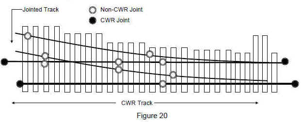
In addition, as long as track owners clearly define the parameters in the CWR plans, the track owner does not need to keep two sets of records (e.g., a record from the § 213.235 inspection and a record from the § 213.119(h)(6)(i) inspection) for inspections of these “adjacent” joints. For example, if the track owner’s CWR plan indicates that joints in crossovers between turnouts must be inspected during the monthly § 213.235 inspection, and a railroad track inspector inspects the joints in the crossover during the monthly § 213.235 inspection, then it is sufficient for the track owner to create and maintain only the § 213.235 record.
FRA believes this option is useful because it avoids the confusion and duplication that might otherwise result. In addition, FRA notes that it would be burdensome for track inspectors to inspect those “adjacent” joints monthly and make a note of the inspection in the monthly § 213.235 record, and also be required to make an additional § 213.119(h)(6)(i) record every few months.
(7) Specify the recordkeeping requirements related to joint bars in CWR, including the following:
(i) The track owner shall keep a record of each periodic and follow-up inspection required to be performed by the track owner’s CWR plan, except for those inspections conducted pursuant to § 213.235 for which track owners must maintain records pursuant to § 213.241. The record shall be prepared on the day the inspection is made and signed by the person making the inspection. The record shall include, at a minimum, the following items: the boundaries of the territory inspected; the nature and location of any deviations at the joint from the requirements of this part or of the track owner’s CWR plan, with the location identified with sufficient precision that personnel could return to the joint and identify it without ambiguity; the date of the inspection; the remedial action, corrective action, or both, that has been taken or will be taken; and the name or identification number of the person who made the inspection.
Guidance: This paragraph addresses the inspection reports that have to be created after periodic inspections required by paragraph (h)(6)(i), and followup inspections as required by the track owner’s CWR plan. The inspection reports of the periodic inspections shall be prepared on the day the inspection is made and are to contain the required information. The periodic inspection record can be combined with other records required pursuant to § 213.241.
(ii) The track owner shall generate a Fracture Report for every cracked or broken CWR joint bar that the track owner discovers during the course of an inspection conducted pursuant to §§ 213.119(g), 213.233, or 213.235 on track that is required under § 213.119(h)(6)(i) to be inspected.
(A) The Fracture Report shall be prepared on the day the cracked or broken joint bar is discovered. The Report shall include, at a minimum: the railroad name; the location of the joint bar as identified by milepost and subdivision; the class of track; annual million gross tons for the previous calendar year; the date of discovery of the crack or break; the rail section; the type of bar (standard, insulated, or compromise); the number of holes in the joint bar; a general description of the location of the crack or break in bar; the visible length of the crack in inches; the gap measurement between rail ends; the amount and length of rail end batter or ramp on each rail end; the amount of tread mismatch; the vertical movement of joint; and in curves or spirals, the amount of gage mismatch and the lateral movement of the joint.
(B) The track owner shall submit the information contained in the Fracture Reports to the FRA Associate Administrator twice annually, by July 31 for the preceding six-month period from January 1 through June 30 and by January 31 for the preceding six-month period from July 1 through December 31.
(C) After February 1, 2010, any track owner may petition FRA to conduct a technical conference to review the Fracture Report data submitted through December of 2009 and assess whether there is a continued need for the collection of Fracture Report data. The track owner shall submit a written request to the Associate Administrator, requesting the technical conference and explaining the reasons for proposing to discontinue the collection of the data.
Guidance: This paragraph requires railroads to generate Fracture Reports that are also required to be submitted to the Associate Administrator twice annually, pursuant to § 213.119(h)(7)(ii)(B). Railroads must complete Fracture Reports when they find cracks or breaks during routine inspections pursuant to §§ 213.119(g), 213.233, or 213.235, on track that is required to be inspected under § 213.119(h)(6)(i). FRA intends to use the Fracture Reports to collect CWR rail joint data; FRA does not intend to use the Fracture Reports for enforcement purposes. Inadvertent errors on Fracture Reports submitted by railroads employees should not be subject to civil penalties. Although, pursuant to § 213.119(h)(6)(i), track owners are not required to complete a Fracture Report for cracks or breaks found in excepted track, Class 1 track, and Class 2 track without passenger service, inspectors should encourage track owners to complete Fracture Reports whenever cracks or breaks are discovered, in addition to the required inspections.
If an FRA inspector encounters repeated failure to prepare and complete reports or comes upon a persistent and recurring pattern of non-reporting, inspectors are to inform their regional specialist of the non-reporting. The regional specialist will confer with Division staff to determine appropriate enforcement action. Track owners are not required to keep the Fracture Reports pursuant to the requirements of § 213.241. However, Fracture Reports should be kept until the track owner has received confirmation from headquarters that the data has been received.
FRA has provided four options as a means for the track owner to submit Fracture Reports. The first option is through an electronic data submission using Extensible Markup Language (XML) format. This option allows the railroad to decide how best to capture the information, yet still submit it to FRA in a standard and valid way. The railroads can submit the information Track and Rail and Infrastructure Integrity Compliance Manual Volume II, Chapter 1 – January 2014 2.1.94
to FRA by sending the XML files directly to FRA via email. The second option, the fillable PDF format, uses a fillable Adobe PDF file to capture and submit the data. The railroad can complete each report and submit the Adobe-generated XML file to FRA via a submit button located on the form. Third, FRA has made available a formatted Excel spreadsheet, into which railroads can input their Fracture Reports. This spreadsheet can be submitted via email, electronic media, or uploaded to the FRA Office of Safety Analysis’ Web site. As a final option, FRA has made a printable version of the OMB-approved Fracture Report form available for download. See Appendix E to this compliance manual for an unofficial copy of the form; however, railroads wishing to submit the form in hard copy should use the fracture report form that is available for download, rather than this unofficial copy. More specific instructions regarding submission of the report are available on the Office of Safety Analysis’ Web site at the following address: http://safetydata.fra.dot.gov/CWR/.
Paragraph (A) requires that the Fracture Report be prepared on the day the cracked or broken CWR joint bar is found. The Fracture Report is to be completed whenever a cracked or broken joint bar is discovered during the periodic inspections required by § 213.119(h)(6)(i), as well as those currently required by §§ 213.233 and 213.235.
The annual million gross tonnage information requested in the Fracture Report can be entered on the report by another designated employee of the railroad, since the railroad track inspector may not have ready access to this information. However, the inspector should be made aware of the range within which the value falls as a result of instructions provided concerning the frequency of inspection required.
Paragraph (B) requires the track owner to submit the information contained in the Fracture Reports twice annually to FRA. FRA is collecting the Fracture Report data and will review and analyze it to better determine the root causes of joint failures.
In addition, FRA inspectors will be expected to submit Fracture Reports when cracked or broken CWR joint bars are found during an inspection that are a defect or an exception to the railroad’s CWR plan, in addition to noting the defect on their report. However, only one Fracture Report is to be submitted for a defective joint. An FRA inspection is not one of the required times that a railroad must submit a Fracture Report. However, the railroad may voluntarily complete the form; therefore, the FRA inspector would not complete and submit the form. Inspectors are to complete their reports on the fillable PDF form, which can be found on the FRA’s Office of Safety Analysis Web site under the "CWR" toolbar tab. The submit button will email the Adobe-generated XML file to a predetermined address.
Paragraph (C) allows any track owner to petition FRA after February 1, 2010, to conduct a technical conference to assess whether there is a continued need for the collection of Fracture Report data. During the technical conference, FRA would review the data collected and the analysis done to date, and determine if sufficient data has been collected to enable FRA to make a technically competent determination of CWR joint bar failure causes and contributing conditions.
(8) In lieu of the requirements for the inspection of rail joints contained in paragraphs (h)(1) through (h)(7) of this section, a track owner may seek approval from FRA to use alternate procedures.
(i) The track owner shall submit the proposed alternate procedures and a supporting statement of justification to the Associate Administrator.
(ii) If the Associate Administrator finds that the proposed alternate procedures provide an equivalent or higher level of safety than the requirements in paragraphs (h)(1) through (h)(7) of this section, the Associate Administrator will approve the alternate procedures by notifying the track owner in writing. The Associate Administrator will specify in the written notification the date on which the procedures will become effective, and after that date, the track owner shall comply with the procedures. If the Associate Administrator determines that the alternate procedures do not provide an equivalent level of safety, the Associate Administrator will disapprove the alternate procedures in writing, and the track owner shall continue to comply with the requirements in paragraphs (h)(1) through (h)(7) of this section.
(iii) While a determination is pending with the Associate Administrator on a request submitted pursuant to paragraph (h)(8) of this section, the track owner shall continue to comply with the requirements contained in paragraphs (h)(1) through(h)(7) of this section.
Guidance: This paragraph permits a track owner to devise an alternate program for the inspection of joints in CWR. A track owner seeking to deviate from the minimum inspection frequencies specified in § 213.119(h)(6) should submit the alternate procedures and a supporting statement of justification to FRA’s Associate Administrator for Railroad Safety/Chief Safety Officer. In the supporting statement, the track owner must include data and analysis that establishes (to the satisfaction of the Associate Administrator for Railroad Safety/Chief Safety Officer) that the alternate procedures provide at least an equivalent level of safety across the railroad.
If the Associate Administrator for Railroad Safety/Chief Safety Officer approves the alternate procedures, the Associate Administrator for Railroad Safety/Chief Safety Officer will notify the track owner of such approval in writing. In that written notification, the Associate Administrator for Railroad Safety/Chief Safety Officer will specify the date that the alternate procedures will become effective. After that date, the track owner shall comply with the approved procedures. If the Associate Administrator for Railroad Safety/Chief Safety Officer determines that the alternate procedures do not provide an equivalent level of safety, the Associate Administrator for Railroad Safety/Chief Safety Officer will disapprove the alternate procedures in writing. While a determination is pending with the Associate Administrator for Railroad Safety/Chief Safety Officer, the track owner shall continue to comply with the requirements contained in § 213.119(h)(6).
Technology (including frequent automated track geometry surveys) and sound CWR management, including prompt removal of "temporary" joints, may provide the additional information required to verify the ongoing integrity of joints in CWR. The alternative procedures provision of this final rule will allow track owners to take advantage of these new approaches as they become available.
(i) The track owner shall submit the proposed alternate procedures and a supporting statement of justification to the Associate Administrator.
(ii) If the Associate Administrator finds that the proposed alternate procedures provide an equivalent or higher level of safety than the requirements in paragraphs (h)(1) through (h)(7) of this section, the Associate Administrator will approve the alternate procedures by notifying the track owner in writing. The Associate Administrator will specify in the written notification the date on which the procedures will become effective, and after that date, the track owner shall comply with the procedures. If the Associate Administrator determines that the alternate procedures do not provide an equivalent level of safety, the Associate Administrator will disapprove the alternate procedures in writing, and the track owner shall continue to comply with the requirements in paragraphs (h)(1) through (h)(7) of this section.
(iii) While a determination is pending with the Associate Administrator on a request submitted pursuant to paragraph (h)(8) of this section, the track owner shall continue to comply with the requirements contained in paragraphs (h)(1) through(h)(7) of this section.
119(i) The track owner shall have in effect a comprehensive training program for the application of these written CWR procedures, with provisions for annual re-training, for those individuals designated under § 213.7(c) as qualified to supervise the installation, adjustment, and maintenance of CWR track and to perform inspections of CWR track. The track owner shall make the training program available for review by FRA upon request.
Guidance: All railroad employees designated under § 213.7(c) as qualified to supervise the installation, adjustment, and maintenance of CWR track and to perform inspections of CWR track must be trained on the track owner’s CWR plan. The track owner shall maintain a written record of this training in accordance with § 213.7(e). Inspectors should refer any requests for training programs to their regional office. Railroad representatives agree to voluntarily make an initial submission of their CWR training programs to FRA. Track inspectors should not request the training program of a specific track owner unless under the specific direction of FRA management. Rather, FRA headquarters staff will undertake the responsibility of obtaining and disseminating this information, as needed, to both FRA inspectors and State inspectors participating in rail safety enforcement activities under Title 49 Code of Federal Regulations (CFR) Part 212. However, inspectors can request a copy of the track owner’s qualification list during regular business hours.
119(j) The track owner shall prescribe and comply with recordkeeping requirements necessary to provide an adequate history of track constructed with CWR. At a minimum, these records must include:
(1) Rail temperature, location, and date of CWR installations. Each record shall be retained for at least one year;
(2) A record of any CWR installation or maintenance work that does not conform to the written procedures. Such record shall include the location of the rail and be maintained until the CWR is brought into conformance with such procedures; and
(3) Information on inspection of rail joints as specified in paragraph (h)(7) of this section.
Guidance: Paragraph (j) contains the recordkeeping requirements for railroads that have track constructed of CWR. At a minimum, a track owner must keep records of the items listed in paragraphs (j)(1) through (j)(3). Paragraph (j)(1) requires each railroad to keep a record of the rail temperature, location, and date of the CWR installations. Paragraph (j)(2) requires a track owner to keep a record of any CWR installation or maintenance work that does not conform with the written procedures. Also, (f)(2) requires the railroad to determine the difference between the average rail temperature and the average rail neutral temperature. This necessitates the recording of rail neutral temperatures at rail repair locations that do not conform to the procedures. Paragraph (j)(3) requires a track owner to keep records of information on inspection of rail joints as specified in paragraph (h)(7).
119(k) The track owner shall make readily available, at every job site where personnel are assigned to install, inspect or maintain CWR, a copy of the track owner’s CWR procedures and all revisions, appendices, updates, and referenced materials related thereto prior to their effective date. Such CWR procedures shall be issued and maintained in one CWR standards and procedures manual.
Guidance: Since the implementation of the CWR regulations, FRA has noted that a number of rail carriers maintain two different sets of CWR procedures. Additionally, some railroads have been maintaining the set of CWR procedures submitted to FRA as required by this section (§ 213.119), as well as a separate set of CWR procedures that is used by personnel in the field. While it may be acceptable for a railroad to instruct its personnel to maintain more restrictive CWR procedures in the field than what is on file with FRA, it is important to note that railroads must train their personnel on the plan formally submitted and filed with FRA. As FRA enforces the track owner’s CWR plan on file with its Office of Railroad Safety, it is critical to have these procedures at every job site where personnel are assigned to install, inspect, or maintain CWR. Specifically, this will ensure that personnel in the field understand which set of procedures FRA will hold them responsible for compliance with the TSS.
119(l) As used in this section—
Adjusting/de-stressing means the procedure by which a rail’s temperature is re-adjusted to the desired value. It typically consists of cutting the rail and removing rail anchoring devices, which provides for the necessary expansion and contraction, and then re-assembling the track.
Annual re-training means training every calendar year.
Buckling incident means the formation of a lateral misalignment sufficient in magnitude to constitute a deviation from the Class 1 requirements specified in § 213.55. These normally occur when rail temperatures are relatively high and are caused by high longitudinal compressive forces.
Buckling-prone condition means a track condition that can result in the track being laterally displaced due to high compressive forces caused by critical rail temperature combined with insufficient track strength and/or train dynamics.
Continuous welded rail (CWR) means rail that has been welded together into lengths exceeding 400 feet. Rail installed as CWR remains CWR, regardless of whether a joint or plug is installed into the rail at a later time.
Corrective Actions mean those actions which track owners specify in their CWR plans to address conditions of actual or potential joint failure, including, as applicable, repair, restrictions on operations, and additional on-foot inspections.[1]
CWR joint means any joint directly connected to CWR.
Desired rail installation temperature range means the rail temperature range, within a specific geographical area, at which forces in CWR should not cause a buckling incident in extreme heat, or a pull-apart during extreme cold weather.
Disturbed Track means the disturbance of the roadbed or ballast section, as a result of track maintenance or any other event, which reduces the lateral or longitudinal resistance of the track, or both.
Mechanical stabilization means a type of procedure used to restore track resistance to disturbed track following certain maintenance operations. This procedure may incorporate dynamic track stabilizers or ballast consolidators, which are units of work equipment that are used as a substitute for the stabilization action provided by the passage of tonnage trains.
Pull apart or stripped joint means a condition when no bolts are mounted through a joint on the rail end, rending the joint bar ineffective due to excessive expansive or contractive forces.
Pull-apart prone condition means a condition when the actual rail temperature is below the rail neutral temperature at or near a joint where longitudinal tensile forces may affect the fastenings at the joint.
Rail anchors means those devices which are attached to the rail and bear against the side of the crosstie to control longitudinal rail movement. Certain types of rail fasteners also act as rail anchors and control longitudinal rail movement by exerting a downward clamping force on the upper surface of the rail base.
1 Note, this term is used in § 213.119(h)(5).
Rail neutral temperature is the temperature at which the rail is neither in compression nor tension.
Rail temperature means the temperature of the rail, measured with a rail thermometer.
Remedial Actions mean those actions which track owners are required to take as a result of requirements of this part to address a non-compliant condition.
Tight/kinky rail means CWR which exhibits minute alinement irregularities which indicate that the rail is in a considerable amount of compression.
Tourist, scenic, historic, or excursion operations mean railroad operations that carry passengers with the conveyance of the passengers to a particular destination not being the principal purpose.
Track lateral resistance means the resistance provided by the rail/crosstie structure against lateral displacement.
Track longitudinal resistance means the resistance provided by the rail anchors/rail fasteners and the ballast section to the rail/crosstie structure against longitudinal displacement.
Train-induced forces means the vertical, longitudinal, and lateral dynamic forces which are generated during train movement and which can contribute to the buckling potential of the rail.
Unscheduled detour operation means a short-term, unscheduled operation where a track owner has no more than 14 calendar days’ notice that the operation is going to occur.
§ 213.121 Rail joints
121(a) Each rail joint, insulated joint, and compromise joint shall be of a structurally sound design and dimensions for the rail on which it is applied.
Guidance: For proper rail load transfer to occur, rail joints must contact the head and base of the rails when the bolts are tight. Many rail joint designs have been used with varying degrees of success, and the TSS does not attempt to single out any particular design as the only acceptable joint. This could inhibit innovation in modern track design.
The TSS requires structural soundness and bolt condition based on maximum authorized train speed. Inspectors must be attentive to locations where standard joint bars are used to join dissimilar rail sections where it would be proper to have compromise bars.
The TSS recognize these important aspects of rail joints and begin this section with a requirement that rail joints have a structurally sound design and dimension for the rail on which they are applied.
Rail joints are considered to be a necessary discontinuity and require special attention by railroad maintenance personnel, railroad inspectors, and FRA inspectors. As far as possible, a rail joint should provide the same relative strength, stiffness, flexibility, and uniformity as the rail itself. The following figure illustrates the proper application of compromise joint bars
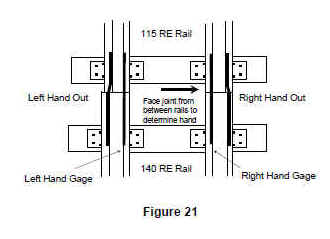
As shown in the following figure, one of the design elements of joint bars to consider is if it’s a head-contact or head-free design:
• The head-contact bar supports the rail ends with a box-type construction, carrying the load between the underside of the head and the base of the rail.
• The head-free joint bar does not contact the underside of the rail heads, but instead contacts the rail in the fillet area. The load distribution is referred to as a triangular load distribution
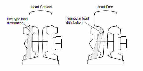
The use of a standard (noncompromise) joint bar of head-contact design on a rail section other than for designed may constitute a deviation. The differences between the head-contact joint bar and the head-free joint bar are significant.
It is evident the joint bar and the rails do not bend or flex exactly with each other along their length. Tests and measurements show that for positive bending, there exists a downward bearing pressure of the under side of the head of the rail on the top surface of the joint bars for some distance along the bar away from the rail ends, (approximately 2 inches). There is also an upward bearing pressure of the upper surface of the base of the rails at parts of the length of the bar further away from the rail end, (bearing distance approximately 3 inches). The converse is true for negative bending.
The head-free joint bar accepts bearing and shear forces from vertical loads in the rail’s upper fillet. A head-contact bar is not designed to fit into the filet. Specifically, the head-contact joint bar accepts bearing from vertical loads on the flat underside of the rail’s head: generally on a 1 to 4 slope. It is not designed to seat into the rail’s upper filet. Although the vertical fishing dimension for the 112 and 115 RE rail sections is identical (33/16 inches), the head filet radius is different:
• For the 115-pound section, radius equals three-fourths of an inch
• For the 112-pound section, radius equals three-eighths of an inch
As shown in the following figure, the 115 head-free bar fits the 112 rail filet practically at a point, most probably inducing joint bar stresses in excess of design which is a deviation from § 213.121(a). The 112 head-contact bar does properly not fit into the 115 rail fillet as it bears in very small areas beneath the head of the rail, possibly inducing joint bar stresses in excess of design and exerting a wedge action between the rail head and rail web, promoting head and web separation. In addition, the joint bar may experience a twist, or torsional force from the tightening of the track bolts when used as a compromise between 115 and 112 rail. The torsional stress from twist will be the greatest at the head and toe of the bar at the rail ends.
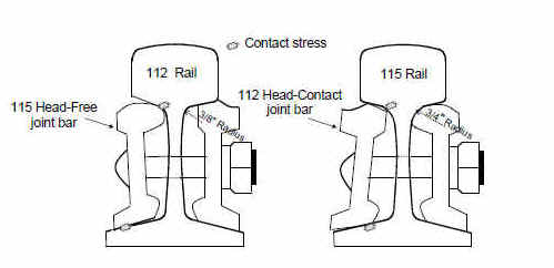
112 Rail115 Rail112 Head-Contact joint barContact stress115 Head-Free joint bar3/8"Radius3/4"Radius
There are exceptions to the use of a joint bar of head-contact design on a rail section other than for designed. For example, a 131-pound or 132-pound head-contact joint bar may be used in lieu of a 131/132 or 131/136 compromise joint bar if rail drilling and joint bar punching is the same. The width of the rail head in these configurations is sufficient to allow full contact in the upper fishing wear surface. In summary:
• 112-pound RE joint bars should not be used as compromise joint bars between 112 RE and 115 RE rail.
• 115-pound RE joint bars should not be used as compromise joint bars between 112 RE and 115 RE rail.
• 131 RE head-contact bars or 132 RE head-contact bars may be used as compromise joint bars between 131 RE and 132 RE rail or 136 RE rail where rail drilling and joint bar punching are the same. (Note: FRA Standards do not prohibit the track owner from field drilling bolt holes to fit).
While the above addresses compromise joint bars, it is stressed that 112 RE bars are not to be used on 115 RE and 119 RE rail and vice versa. Joint bars with 131 RE head-free and 132 RE head-free design, or 131 RE head-free and 136 RE head-free joint bars, are not interchangeable and are not to be intermixed.
For a compendium of rail section dimensions in order to compare other rail sections for compatibility between joint bars on various rail sections refer to Appendix C of this manual.
121(b) If a joint bar on Classes 3 through 5 track is cracked, broken, or because of wear allows excessive vertical movement of either rail when all bolts are tight, it shall be replaced.
Guidance: Joint bars are designed to fit into the space between the bottom of the rail head and rail base (fishing). With the bolts tight, the joint bars are wedged into the fishing space to provide lateral and vertical beam strength thereby supporting the abutting rail ends. When held up against the rail with bolts, joint bars contact the rail at two points; bottom of the rail head (or fillet) and top of the rail base. These contact points, known as the "fishing surfaces," can experience metal loss due to abrasion and mechanical wear that occurs during the cyclical train dynamic loading. After long-term service, the fishing surfaces of the rails and bars can wear to the point that joint bars are no longer wedged into the rail, even with tight bolts. In such cases, the joint assembly will no longer optimally support the abutting rail ends.
Joints with minimally worn fishing surfaces can provide for the safe passage of wheels in Classes 1 through 5. As a guide, excessive vertical movement would exist when there is significant fishing surface wear and wheel loads cause the abutting rail ends to exhibit tread mismatch approaching the thresholds under § 213.115. If excessive vertical movement occurs, or there are any cracks, corrective action would be to replace the bars or take other proper corrective action.
Proper corrective action for a joint bar cracked or broken, other than center break, in Classes 3 through 5 track, would be replacement or a reduction to Class 2. If both joint bars are cracked or broken between the 1st and 2nd bolt hole (including through the 2nd bolt hole), it should be considered Class 1. This is because there is only one bolt in a rail end that is within the remaining section of the joint bar that is providing support.
121(c) If a joint bar is cracked or broken between the middle two bolt holes it shall be replaced.
Guidance: For a center cracked or broken bar, the appropriate corrective action would be replacement or reduction to Class 1 speeds under the provisions of § 213.9(b).
121(d) In the case of conventional jointed track, each rail shall be bolted with at least two bolts at each joint in Classes 2 through 5 track, and with at least one bolt in Class 1 track.
Guidance: Track owners must have the number of required bolts in each rail in a joint. This paragraph does not prescribe a tightness (torque) standard for each bolt. A bolt that no longer can support the joint bar against the rail will continue to provide resistance to pull aparts when the rail is in tension. The ability of the bolts to hold bars against the rail to support the abutting rail ends is covered under § 213.121(f).
A bolt does not fulfill the requirements of this paragraph if it is in imminent danger of complete failure (it no longer is holding the bar to the rail and no longer resists pull apart forces). For example, the nut is missing (it will likely fall out under subsequent train movements) or the bolt shaft is fractured.
121(e) In the case of continuous welded rail track, each rail shall be bolted with at least two bolts at each joint.
Guidance: Rail installed as CWR remains as CWR, regardless of whether a joint or plug is installed at a later time. If there is only one bolt in a rail end at a joint, in a CWR string, that one bolt will be subject to all the tensile axial forces and will easily shear (break) resulting in a pull-apart.
121(f) Each joint bar shall be held in position by track bolts tightened to allow the joint bar to firmly support the abutting rail ends and to allow longitudinal movement of the rail in the joint to accommodate expansion and contraction due to temperature variations. When no-slip, joint-to-rail contact exists by design, the requirements of this paragraph do not apply. Those locations when over 400-feet in length, are considered to be continuous welded rail track and shall meet all the requirements for continuous welded rail track prescribed in this part.
Guidance: If the joint bars are loose, the joint is not in compliance with § 213.121(f). In addition, a joint assembly is not in compliance when inadequately tightened bolts prevent it from supporting the abutting rail ends under the expected traffic loads.
Joint bolts can deteriorate sufficiently as to create a condition where the bars may become completely detached from the rail or cause a total lack of support, which can contribute to a broken rail. Such a condition can create a mismatch which exceeds the limits specified in § 213.115 (Rail end mismatch). In such a case, the defect would be rail end mismatch (class specific) and inspectors should also include a notation about the loose joint bars.
This paragraph also recognizes the design characteristic that enables the rail ends in a joint to move longitudinally to handle temperature changes (expansion/contraction) or rail creep (traffic flow). This type of joint bar assembly is standard for jointed rail because that type of track construction has lower axial forces than CWR. In CWR, it is desirable to contain the rail expansion and contraction in the remaining joints (i.e., insulated joints) in order to eliminate the pull-apart action that occurs in regular joints. In CWR, the track structure, by design, dissipates the axial forces. Accordingly, this paragraph allows joint designs that stop the axial rail movement within the assembly.
Except for the axial movement component of this paragraph, joint bars such as glued insulated joints are subject to all of the remaining requirements of this paragraph and all other paragraphs of § 213.121. These types of assemblies are considered to be joints, even in CWR (see § 213.119). However, for the definition as to what constitutes CWR, a glued joint is not a longitudinal discontinuity in a rail string. Glued joints are also considered joints under § 213.109 with respect to the required positioning of nondefective ties at joints.
121(g) No rail shall have a bolt hole which is torch cut or burned in Classes 2 through 5 track.
Guidance. This paragraph prohibits the use of a rail containing a bolt hole that has been torch cut or burned in Classes 2 through 5 track.
121(h) No joint bar shall be reconfigured by torch cutting in Classes 3 through 5 track.
Guidance. This paragraph prohibits the reconfiguration of joint bars by torch cutting in Classes 3 through 5 track. By omission of the reference to Classes 1 and 2 track, this practice of reconfiguration is allowed in those classes. However, the joint bars that are reconfigured by torch cutting must meet certain criteria for structural soundness of design and dimension, which is required under (a) of this section.
§ 213.122 Torch cut rail
122(a) Except as a temporary repair in emergency situations no rail having a torch cut end shall be used in Classes 3 through 5 track. When a rail end is torch cut in emergency situations, train speed over that rail end shall not exceed the maximum allowable for Class 2 track. For existing torch cut rail ends in Classes 3 through 5 track the following shall apply –
(1) Within one year of September 21, 1998, all torch cut rail ends in Class 5 track shall be removed;
(2) Within two years of September 21, 1998, all torch cut rail ends in Class 4 track shall be removed; and
(3) Within one year of September 21, 1998, all torch cut rail ends in Class 3 track over which regularly scheduled passenger trains operate, shall be inventoried by the track owner.
Guidance. The regulation prohibits the torch cutting of rail ends in Classes 3 through 5 track except as a temporary repair in emergency situations. In such emergency situations, train speed shall not exceed the maximum allowable for Class 2 track.
Existing torch cuts must be removed from track in the following time frames:
• Class 5 track – by September 21, 1999.
• Class 4 track – by September 21, 2000.
• Class 3 track with passenger trains – by September 21, 1999, all torch cuts shall be inventoried by the track owner.
122(b) Following the expiration of the time limits specified in (a)(1), (2), and (3) of this section, any torch cut rail end not removed from Classes 4 and 5 track, or any torch cut rail end not inventoried in Class 3 track over which regularly scheduled passenger trains operate, shall be removed within 30 days of discovery. Train speed over that rail end shall not exceed the maximum allowable for Class 2 track until removed.
Guidance. Those torch cuts inventoried will be “grandfathered in” and any torch cuts found after the expiration of one year that are not inventoried must be slow ordered to Class 2 speed and removed within 30 days of discovery. If a railroad chooses to upgrade a segment of track to Class 3, and passenger trains are operated, all torch cuts must be removed before speeds can exceed the maximum for Class 2 track. If a railroad chooses to upgrade a segment of track from any lower class to Class 4 or 5, it must remove all torch cuts.
§ 213.123 Tie plates
123(a) In Classes 3 through 5 track, where timber crossties are in use, there must be tie plates under the running rails on at least 8 of any 10 consecutive ties.
123(b) In Classes 3 through 5 track no metal object which causes a concentrated load by solely supporting a rail shall be allowed between the base of the rail and the bearing surface of the tie plate. This paragraph (b) is applicable September 21, 1999.
Guidance. Inspectors should consider this section jointly with the requirements for crossties and rail fastenings and report tie plate conditions as defects where safety is impaired by the absence of tie plates.
In Classes 3 through 5 track no metal object that causes a concentrated load by solely supporting a rail shall be allowed between the base of rail and the bearing surface of the tie plate. The specific reference to “metal object” is intended to include only those items of track material that pose the greatest potential for broken base rails such as track spikes, rail anchors, and shoulders of tie plates. The phrase “causes a concentrated load by solely supporting a rail” further clarifies the intent of the regulation to apply only in those instances where there is clear physical evidence that the metal object is placing substantial load on the rail base, as indicated by a lack of loading on adjacent ties.
§ 213.127 Rail fastening systems
(a) Track shall be fastened by a system of components that effectively maintains gage within the limits prescribed in § 213.53(b). Each component of each such system shall be evaluated to determine whether gage is effectively being maintained.
Guidance: "Rail fastening systems" include modern-day elastic fastening systems, which can consist of abrasion pads, insulator clips, shoulder inserts cast into concrete ties, as well as the fastener itself, of which many different designs are in use today. The fastening system can also be of the traditional cut spike variety, with or without tie plates. The failure of certain critical components within a particular system could adversely affect the ability of the individual fastener to provide adequate gage restraint. The wording of this regulation provides for an evaluation of all components within the system, if necessary, when degradation of the fastening system has resulted in problems maintaining gage within the limits prescribed in § 213.53(b).
When an inspector identifies a gage geometry condition where the fastener system has degraded and the location in question meets the factors described below, the inspector must examine each component of the fastener system (e.g., clip, insulating pad, bolts, spiking pattern, etc.). The inspector should describe the nature of the failed components on the F6180.96 form. If a fastener condition causes the gage to exceed the limits of § 213.53, the inspector shall report the condition as a gage defect and describe the nature of the fastener condition on the same defect line of the report.
This section requires the inspector to exercise judgment in evaluating the condition of fasteners. The following factors should be considered in the evaluation:
• Gage exceeding the limits of § 213.53 (in such cases gage and track class will govern).
• Gage close to the limits of § 213.53 with evidence of recent widening.
• Evidence of recent rapid deterioration of gage with probable continued deterioration.
• Evidence of recent significant damage to rail fasteners to the extent that gage widening is probable.
• Evidence of recent maintenance work improperly performed resulting in lack of sufficient fasteners to prevent gage widening under expected traffic.
• Traffic conditions, including speed, tonnage, and type of equipment.
• Conditions of curvature and grades.
FRA inspectors may use a PTLF described in § 213.110 for the purposes of measuring the effectiveness of fasteners. Refer to Appendix D - PTLF instructions for non-GRMS territory under § 213.53.
A unique attribute of concrete crossties is the abrasion that can occur between the base of the rail and the rail-seat on the crosstie, a component of the rail fastening system. A variety of tie pad designs and materials are placed between the rail and the ties to mitigate abrasion. However, unequal or "wedged" abrasion of the rail seat can be problematic for a high-speed or high-tonnage operating environment that may cause rail fasteners to become loose under load or in extreme cases cause rail-tilt or rollout. See the following figure. Accordingly, inspectors should look for rail rollout due to rail seat abrasion on concrete crossties, particularly in territory with heavy traffic levels and moderate curvature. The mechanics of this condition on concrete crossties include the following elements:
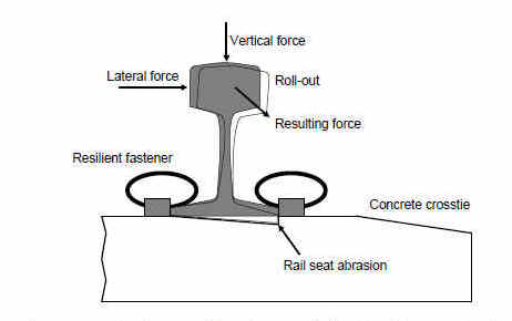
• Concrete wear or abrasion resulting in loose rail clips, insulators, and pads.
• Loose components allow more moisture and abrasives to enter rail seat.
• Once the field side of the rail base wears through the tie pad and contacts the concrete tie rail seat, rapid cutting into the concrete (accelerated abrasion) can occur.
• Signs and symptoms of concrete crosstie rail seat abrasion include.
• Tie pad crushed or squeezed out (maintaining integrity of the tie pad is essential).
• Insulators crushed, moving, or missing.
• Clips loose indicating loss of pressure on the rail base (loss of toe load).
• Longitudinal rail movement.
• Indications of cement colored paste in the ballast from the abraded rail seat.
• Metal flaking or grease streaks in the center of the low rail in a curve caused by the outer rim of wheel (or false flange) placing excessive pressure on the head of the rail, a condition generally created by gage-widening.
Based on the above discussion, it is apparent that rail-seat abrasion on concrete ties causes rail rollout. As rail rollout occurs, it decreases the effectiveness of the rail fasteners and will often lead to gage geometry conditions. As a general rule, inspectors should cite this condition as a rail fastener defect (213 defect code 0127A). However, where rail rollout causes the gage to exceed the threshold for the designated class of track, inspectors should cite this condition as a gage defect (see § 213.53).
Rail anchors are not considered to be a rail fastener. In areas where rail anchors are used in combination with resilient fasteners on concrete ties, the resilient rail fasteners that normally perform a dual function to restrain rail laterally and longitudinally should only be evaluated on their ability to provide lateral restraint to prevent gage-widening in regard to this section.
An insufficient fastener defect should be written when an unsafe condition results from missing or defective fasteners (e.g., heads of cut spikes sheared off at throat) on otherwise supportive crossties.
(b) If rail anchors are applied to concrete crossties, the combination of the crossties, fasteners, and rail anchors must provide effective longitudinal restraint.
Guidance: This paragraph requires that if rail anchors are applied to concrete crossties, then the combination of the crossties, fasteners, and rail anchors must provide effective longitudinal restraint. "Effective longitudinal restraint" is a performance-based standard.
(c) Where fastener placement impedes insulated joints from performing as intended, the fastener may be modified or removed, provided that the crosstie supports the rail.
Guidance: addresses instances where fastener placement impedes insulated joints from performing as intended by permitting the fastener to be modified or removed, provided that the crosstie supports the rail. "Support" means that the crosstie is in direct contact with the rail or leaves an incidental space between the tie and rail. Certain joint configurations do not permit conventional fasteners to fit properly. As a result, manufacturers offer a modified fastener to fit along the rail so that the fastener provides the longitudinal requirement, or it is removed completely, providing lateral restraint is accomplished by ensuring full contact with the rail or additional placement of anchors on the base of the rail.
Additionally, FRA notes that the requirement of having an effective crosstie within a prescribed distance of a joint contained in § 213.109(e) would apply, without modification for insulated joints. FRA has not mandated what type of equipment or what manufacturer a track owner must use, but instead has determined to regulate the performance of the material to the minimum safety standards promulgated in Part 213.
§ 213.133 Turnouts and track crossing generally
133(a) In turnouts and track crossings, the fastenings must be intact and maintained so as to keep the components securely in place. Also, each switch, frog, and guardrail must be kept free of obstructions that may interfere with the passage of wheels.
Guidance. There are several types of fastenings, which include reinforcing straps, connecting rods, rail hold down clips, and braces. (For a more extensive compilation of fastenings, see the fasteners listed in defect codes 213.133. Where fastenings are loose or missing, inspectors should cite the railroad using 213 defect code 0133A15 (Turnout or track crossing fastenings not intact or maintained.) In addition, where fasteners are loose or missing and there is an apparent contributing condition (e.g., a large section of the casting is broken out at an at-grade rail to rail crossing), inspectors should include a description of that contributing condition in their inspection report.
133(b) Classes 3 through 5 track shall be equipped with rail anchoring through and on each side of track crossings and turnouts, to restrain rail movement affecting the position of switch points and frogs. For Class 3 track, this paragraph (b) is effective September 21, 1999.
133(c) Each flangeway at turnouts and track crossings must be at least 1½ inches wide.
Guidance. A turnout is a track arrangement consisting of a switch and frog extending from the point of the switch to the heel of the frog. This arrangement allows engines and cars to pass from one track to another. Because of the operating or movable parts and lateral thrust, it is essential that fastenings be in place, tight, and in sound condition.
A track crossing (diamond) is an assembly used where two tracks intersect at grade permitting traffic on either track to cross the rails of the other. It may consist of four frogs connected by short rails, or a plant manufactured “diamond.” Because of the impact a crossing is subjected to, it is essential that fastenings be in place, tight, and in sound condition. Each switch, frog, and guardrail must be kept free of obstruction.
Anchors on each side of a turnout or crossing and through a turnout are required on Classes 4 through 5 track. For Class 3 track, this requirement is effective on September 21, 1999. In determining the adequacy of anchors at and on each side of a turnout or crossing and through turnouts, inspectors should determine the capability of these devices to:
• Restrain rail.
• Assure proper fit of switch points.
• Prevent line irregularities.
Ties and timbers at switches and crossings must be of sound condition, well-tamped, and the roadbed must be adequately drained.
Flangeways at turnouts and track crossings must be at least 1½ inches wide.
Turnouts and track crossings must be walked and measurements made before they can be included on the F6180.96 form as a unit inspected.
§ 213.135 Switches
135(a) Each stock rail must be securely seated in switch plates, but care shall be used to avoid canting the rail by overtightening the rail braces.
Guidance. The TSS under § 213.135 specifies the requirements for switch restraint, movement, and fit. Each stock rail must be securely seated in the switch plates. Various conditions, such as loose braces or hanging ties, can cause a stock rail to become unseated. In these situations, inspectors should cite the railroad with 213 defect code 0135A1. Alternatively, a stock rail can become unseated if the braces are overtightened during maintenance. In these situations, inspectors should cite the railroad with 213 defect code 0135A2.
135(b) Each switch point shall fit its stock rail properly, with the switch stand in either of its closed positions to allow wheels to pass the switch point. Lateral and vertical movement of a stock rail in the switch plates or of a switch plate in a tie shall not adversely affect the fit of the switch point to the stock rail. Broken or cracked switch point rails will be subject to the requirements of §213.113, except that where remedial actions C, D, or E require the use of joint bars, and joint bars cannot be placed due to the physical configuration of the switch, remedial action B will govern, taking into account any added safety provided by the presence of reinforcing bars on the switch points.
Guidance. This paragraph recognizes the existence of reinforcing bars or straps on switch points where joint bars cannot be applied to certain rail defects, as required under § 213.113(a)(2), because of the physical configuration of the switch. In these instances, remedial action B will govern, and a person designated under § 213.7(a), who has at least 1 year of supervisory experience in track maintenance, will limit train speed to that not exceeding 30 mph or the maximum allowable under § 213.9(a) for the appropriate class of track, whichever is lower. Of course, the person may exercise the options under § 213.5(a) when appropriate.
Section 213.135(b) addresses cracks in the switch rail (point) with reinforcing straps acting as surrogate joint bars. If the switch point rail is not cracked, and only the straps are cracked, then it is not appropriate to cite § 213.135(b); and inspectors should cite the appropriate defects under § 213.133(a). Normally, minor cracks in a strap are not a major concern. However, if a strap is fully broken and causing other problems (e.g., loose switch clip, etc.), then § 213.133 (Turnouts and track crossing generally) would be appropriate. If the straps and switch point rail are both broken, then there is an unprotected rail break and inspectors should cite the appropriate defect under § 213.113.
Most industry standards call for a 4¾-inch opening between the switch point and the stock rail, measured at the No. 1 switch rod. As components wear, “lost motion” will result. When the problem of elongated switch clip and/or rod holes is encountered, the switch rods may be adjusted at the clip (e.g., adjustable side jaw clips, rocker clips, etc.). Adjustment may also be accomplished at the switch stand depending on the design of the assembly. In some cases, lost motion may be compensated by the addition of properly designed shims between the switch clip assembly and the switch rail.
When the opening is substantially less than the standard dimension, wheels can still pass through the switch as intended. However, the backs of wheels may contact the inside rail head of the open switch rail. This interaction can cause undesirable lateral pressure against the switch rail. This pressure can contribute to broken heel block bolts, cause cracked or broken switch clips, and broken switch crank cross pins. In extreme circumstances, the closed point can open under movement because of the transfer of lateral loads through the switch rods. In these circumstances, inspectors should make an extra effort to determine the condition of all affected components. The amount of throw is one of the many factors that must be taken into consideration when determining the railroad’s compliance with § 213.133 and § 213.135.
Based on the above, make sure that switch points fit snugly against the rail when the switch is thrown in either position. As appropriate, request that the railroad representative operate the switch to test for lost motion and/or loose connections.
The Appendix to the American Railway Engineering and Maintenance of Way Association (AREMA) Portfolio of Trackwork Plans contains the following split switch terms:
• “Split Switch with Uniform Risers - A split switch in which the switch rails have a uniform elevation on riser plates for the entire length of the switch, and therefore not having a heel slope, the point rail rise being run off back of the switch in the closure rails.”
• “Split Switch with Graduated Risers - A split switch in which the switch rails are gradually elevated by means of graduated riser plates until they reach the required height above the stock rail, and therefore having a heel slope.”
The heel of the switch point is higher than the stock rail at the heel joint with the uniform riser layout while, on the graduated layout, the switch point is at the same elevation as the stock rail. The mixing of uniform riser and graduated riser plates in the same switch, while not specifically addressed in the TSS, can cause undesired stress in the switch rails and closure rails. Inspectors should make a note of the intermixing of switch plates in turnouts that have a high amount of traffic.
135(c) Each switch shall be maintained so that the outer edge of the wheel tread cannot contact the gage side of the stock rail.
Guidance: : Inspectors are to examine the seating of stock rails in the switch plates to ensure that the outer tread of a wheel cannot engage the gage side of these rails. Grease lines or slight groves running at a slight angle on the tread of a stock rail can provide inspectors with clues about the wheel/rail interface. These marks can be found in the area where wheel treads transition from the switch rail to the stock rail. When found, inspectors should closely examine the gage side of the stock rail to make sure the outer edge of wheel treads are not contacting the gage side of the stock rail. As shown in the following figure, this type of defect can occur when a worn switch rail and switch plates remain in place after a stock rail has been renewed. This causes the switch rail to drop down from the same level as its corresponding stock rail. The danger associated with this condition is the possibility that the outer edge of a wheel can contact the gage side of the stock rail during a trailing movement through a switch, thereby turning over the stock rail.
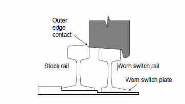
Other items that can cause outer edge wheel contact include improper surface, poor crosstie condition, loose rail braces, stock rails not securely seated, switches where the majority of the traffic uses one side of the turnout, and insecure jointed heel blocks with improper elevation.
135(d) The heel of each switch rail shall be secure and the bolts in each heel shall be kept tight.
Guidance. At least two tight bolts in each rail are required to ensure that the heel of each switch rail is “secure” for purposes of determining compliance with § 213.135(d). Examine the heel block, its fastenings, and bars; or, in the absence of a heel block, (which is known as a floating heel block) examine that assembly.
If heel joints were considered to be a normal joint, only one bolt per rail end would be required in the heel for Class 1 track. However, the heel joint functions in a different manner than a normal track joint. The heel joint serves as the pivotal point for the rotation of the switch point. It helps maintain the proper horizontal, vertical, and longitudinal fit of the switch point against its stock rail. One bolt per rail end in Class 1 track at the heel joint does not provide redundancy. The loss of the single bolt in the rail end at the heel joint could have serious safety consequences.
Some railroad heel joints have as many as six bolts for the higher track classes. Typically, when railroads plan to field weld, they do not drill the middle two bolt holes in the rail of a six-hole joint bar. This practice, which provides for at least two bolts in each rail end of the heel, satisfactorily secures the assembly.
The switch heel assembly with joint bars also performs the function of a joint. As such, where there is an improper joint bar at a heel block, an inspector should cite § 213.121 (Rail joints). One example of an improper joint bar is the installation of a six-hole joint bar where a five-hole bar, by design, should be used. This would be a deviation of § 213.121, because it is an improperly designed bar for that application, which may make it difficult to throw the switch or may cause gapping.
135(e) Each switch stand and connecting rod shall be securely fastened and operable without excessive lost motion.
Guidance. For hand-operated switch stands of virtually all types, rotary motion imparted to the vertical spindle within the stand by the person operating the hand lever is translated into (practically) linear movement of the connecting rod by the right angle combination of the end of the spindle beneath the stand and its attached crank. Unless cranks are integrated with the spindle by casting during manufacture, they are separate pieces that must be joined. Cranks are attached to spindles in one of two ways: (1) they may be turned into a threaded opening in the side of the spindle or (2) the crank may be fabricated to have a square or rectangular smooth opening at one end, which can be moved from below, up onto a spindle having a similar cross-section to a position where it can be secured in place by a horizontally inserted cross pin that simultaneously engages the crank with the spindle. For ease of reference in this discussion, the first case will be referred to as Type A and the second case as Type B. An undesired decoupling of the connecting rod and the switch stand can occur in Type A if the bolt attaching a connecting rod to a threaded crank comes out and, in Type B, separation of the crank and the spindle can occur in the absence of the cross pin. Either instance could result in the gapping of the closed switch point under train movement, unless some other device is in place to physically restrain the points.
Type B switch stands may at times have a plate-like arrangement of sheet metal suspended from the headblock timbers beneath the assembly. This device, generally a shallow “U” shape, is commonly referred to as a “safety plate.” The function of the plate is twofold: (1) to restrict the downward movement of the crank on the spindle, should the cross pin be absent, so the crank does not completely separate from the spindle, and (2) to keep a vertically unrestrained crank from sliding down the spindle far enough to permit the connecting rod enough space below the bottom of the switch stand to move up off the lug of the crank. There have been cases where cross pins have fractured. The plate itself is deformed so that the downward displacement of the crank was sufficient to enable the connecting rod to clear the crank lug without contacting the base of the stand. This leads to decoupling of the switch stand and the connecting rod.
Inspectors must constantly bear in mind those aspects of switch stand performance that are crucial to functional safety. This discussion concentrates on that region of the mechanical linkage between the switch points and the switch stand that may be difficult to observe in the course of a turnout inspection.
There are several different styles of Type B switch stands that are in use on main tracks and yards in the railroad industry. These models differ in minor ways. Nevertheless, they rely on the cross pin restraint of the spindle/crank subassembly and they all share vulnerability to the uncoupling of the switch stand and connecting rod. A turnout inspection must include examination of these hard to see parts even.
Inspectors should examine the effectiveness of the fastening system of the switch stand to the head block ties and look for signs of movement of the switch stand which can result in loss motion leading to a gapped switch point.
135(f) Each throw lever shall be maintained so that it cannot be operated with the lock or keeper in place.
Guidance. Inspectors must
examine each switch lock and keeper. Certain types of switch stands “internally
toggle” when the handle is thrown all the way in either position to hold the
switch point against its stock rail. These types of switch stands are used in
other than main track and often are a “semi-automatic” design whereby a
train trailing the turnout, with the switch in the incorrect position, will
initially force the points over. The final throw is completed by the internal toggling action of the switch stand. By design
and application preference, these switch stands might not have a lock or keeper
for other than main track applications (see the following figure).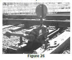
There is a concern associated with this type of switch stand retrofitted with an “S”-shaped strap, bolted and welded to one of the two flanges of the throw lever stop. The bolt has been proven to be ineffective in preventing rotation of the strap, and the bead weld, placed by the manufacturer at the top of the strap, cracks from repeated depression of the keeper. The strap rotates downward, altering the location of the lock shackle or keeper, allowing the throw of the switch lever without removal of the lock or keeper.
If the above types of switch stands are used at switches and derails not requiring securing, the soundness of the strap is not in question. However, if the track owner requires that the stand be secured by lock or keeper, a weld displaying cracks will call into question the soundness of the latch mechanism and 213 defect code 0135F, throw lever (potentially) operable with switch-lock or keeper in place, should be cited without recommending a violation. If the track owner fails to aggressively address and correct the potential defect on the subject types of switch stands, consider recommending a violation to Chief Counsel.
49 CFR 218.105(b) requires that all hand operated main track switches are to be locked. An ineffective or worn latch or hasp can allow the throw lever of the switch to be operated with the lock in place. There are several different types and models of hand operated switches in use; Inspectors should inspect each latching mechanism to for wear and possible operation of the throw lever with the lock in place. The inspection should include stepping on the latch and observation of the clearance between the throw lever and the opening created when the latch is depressed with lock in place. Inspectors should not attempt to raise the operating lever and request the accompanying railroad representative to lift the handle if its operation through the latch appear probable, and it is safe to do so. As shown in figure below, the throw lever is clearly operable with the lock in place.
Many power switches are operable by either power (remotely by control operator or train dispatcher) or by hand, frequently called dual control switches. Inspection of this type of switch machine is similar to the typical hand operated switch stand. Most have two levers, one to remove the switch machine from power operation, and one that acts as the throw lever. The latches should be inspected for the possibility of the power lever or throw lever being operated with the lock in place. (See the following two figures)
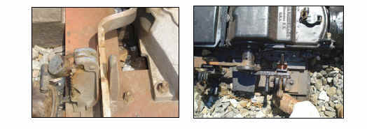
135(g) Each switch position indicator shall be clearly visible at all times.
Guidance. Examine condition of switch position indicator and note any unnecessary obstruction to its visibility. This requirement does not mandate that every switch have a position indicator but merely requires such devices to be clearly visible when installed on a switch stand.
135(h) Unusually chipped or worn switch points shall be repaired or replaced. Metal flow shall be removed to insure proper closure.
Guidance. The rule does not provide for specific dimensions for determining when switch points are “unusually chipped or worn.” The accident/incident database indicates that worn or broken switch points are the largest single cause of derailments within the general category of “Frogs, Switches, and Appliances.” However, most of these derailments are related also to other causal factors such as wheel flange condition, truck stiffness, and train-handling characteristics. Therefore, qualified individuals must use their experience to determine when switch points are “unusually chipped or worn.”
135(i) Tongue & Plain Mate switches, which by design exceed Class 1 and excepted track maximum gage limits, are permitted in Class 1 and excepted track.
Guidance. This paragraph provides an exemption for this item of specialized track work, primarily used in pavement or street railroads, which, by design, does not conform to the maximum gage limits prescribed for Class 1 and excepted track. This type of special work is fabricated from “girder rail,” which includes a tram (flangeway) rolled into the rail section. A “mate” is similar to a frog but located on the side of the switch that is equivalent to a straight stock rail. The switch, when in the open or curved position, guides wheels past the mate on the turnout (curved) side in a manner similar to a frog guardrail.
Guidance, General. In addition to considering the above criteria, inspectors must perform the following when inspecting switches:
• Check alinement, gage, and surface.
• Examine condition as to the wear of switch points and stock rails.
• See that all bolts, nuts, cotter pins, and other fastenings are in place, in good condition, and are properly tightened;
• See that switch points fit snugly against the rail when the switch is thrown in either position. Request that the railroad representative operate switches to test for lost motion and/or loose connections.
• If applicable, examine the rod and fastenings that connect the switch point to the switch circuit controller to ensure they are in place and in good condition.
• Examine the condition and support of spring and power-switch machines and hand-thrown switch stands, including automatic or safety switch stands. Switch stand and machine fastenings to the head block ties must be tight to avoid any movement or play.
• Examine switch-lock and keeper.
• Examine condition of switch position indicator and note any unnecessary obstruction to its visibility.
• Examine the heel block, its fastenings, and bars; or, in the absence of a heel block, examine the floating heel of the switch point.
• Examine the seating of stock rails in the switch plates to ensure that the outer tread of a wheel cannot engage the gage side of these rails and that chairs or braces do not cant these rails in. This defect is particularly a problem for travel in the direction from the frog to the switch (trailing movement). Grease lines or slight groves running at a slight angle on the tread of a stock rail can provide inspectors with clues about the wheel/rail interface. These marks can be found in the area where the wheel tread transitions from the switch rail to the stock rail. When found, inspectors should closely examine the gage side of the stock rail to make sure the outer edge of wheel treads are not contacting the gage side of the stock rail.
• Examine the gage plates and switch rods.
§ 213.137 Frogs
137(a) The flangeway depth measured from a plane across the wheel-bearing area of a frog on Class 1 track may not be less than 1⅜ inches, or less than 1½ inches on Classes 2 through 5 track.
Guidance. The Association of American Railroads (AAR) Field Manual of Interchange Rules states that a wheel is condemnable when the flange height is “1½ inches or more above the approximate center line of the tread.” The AREMA Portfolio of Trackwork Plans, Point and Flangeway Dimensions, provides a designed flangeway depth of at least 1¾ inches. Therefore, the amount of clearance between a worn wheel with a high flange and the bottom of a new frog’s flangeway may be as little as three-eighths inch. At higher speeds, if a worn frog has a flangeway less than 1½ inches, the wheel flange could “bottom out” in the flangeway and result in severe damage to the frog.
Section 213.137(a) permits a flangeway depth of 1⅜ inches in Class 1 track. In such a condition, a wheel that is approaching condemning limits might contact the bottom of the flangeway. As such, it is possible to have evidence of wheel flangeway contact on the bottom of the flangeway caused by noncompliant wheels.
137(b) If a frog point is chipped, broken, or worn more than
⅝ inch down and six inches back, operating
speed over that frog may not be more than 10 m.p.h.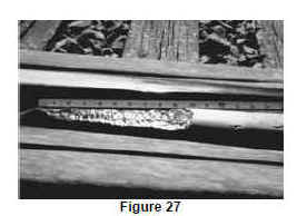
Guidance. If a frog point is chipped, broken, or worn more than five-eighths inches down and 6 inches back, a collapse of the point area is possible after repeated wheel impacts. This parameter requires a defect to be more than five-eighths inches down from the original profile to a location 6 inches back toward the heel to be considered. For example, a frog point that is seven-eighths inches below its original profile at the actual frog point and seven-eighths inches below at a position 6 inches back toward the heel of the frog would be a defect.
For a severe condition that would not meet this criteria such as a breakout at a frog point that is only 4 inches in length and greater than five-eighths inches down, inspectors may consider using the 213 defect code 0137E.
While this condition may not be a defect, it is a method to notify a railroad of a condition that the inspector feels the structural integrity of the frog is in question. Please note that 213 defect code 0137E does not link to a paragraph in the TSS and may only be used as an advisory to the railroad.
Another possible result of a severely worn frog point, especially when coupled with a worn or loose guardrail, is that a railroad wheel may “hit” the point and climb to the wrong side of the frog. Also see Figure 27 for information about “depressed point” designs that may influence the measurement of a worn or broken frog point.
137(c) If the tread portion of a frog casting is worn down more than ⅜ inch below the original contour, operating speed over that frog may not be more than 10 m.p.h.
The tread of the frog is considered to be any portion that is contacted by the tread of the wheel except for portion of the frog from the actual point to a position 6 inches back towards the heel [this area is addressed by § 213.137(b)]. As shown in the following figure, the measurements of the portion of the tread further back than the 6 inch position may be taken by placing a straightedge positioned transversely. The following figure shows a rail bound manganese frog design with an actual frog point that is three-sixteenths inch lower than the tread portion. A frog built without manganese insert (e.g., a frog composed of Tee rails called a bolted rigid frog) will have a point with a similar profile. Called a depressed point, the tread will taper up to the top of the rail profile in the direction toward the frog heel in varying distances depending upon the different manufacturing designs and size of frogs, but not less than 5 inches.
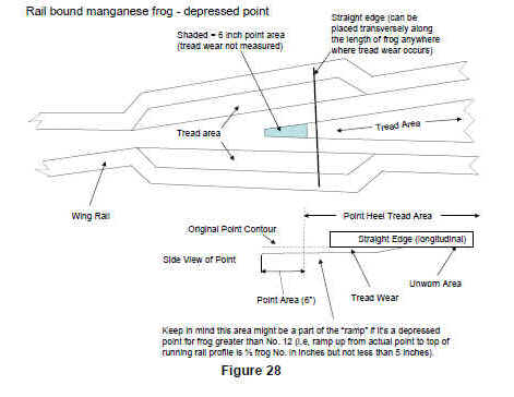
An alternate rail bound manganese or solid cast frog design includes a profile whereby the tread portion of the casting adjacent to a frog point is manufactured to a plane one-eighth inch above the top of the rail profile (wing wheel riser). See following figure. These design characteristics need to be considered when measuring tread wear as discussed below.
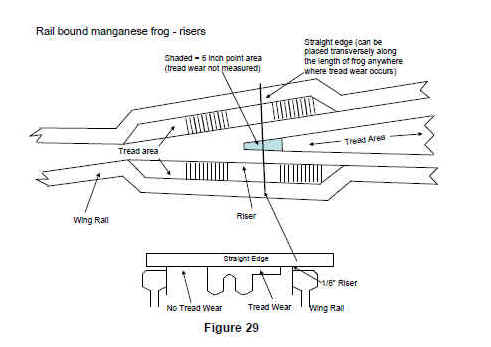
When measuring tread wear, the distance from the bottom of the straight edge to the worn tread at the riser is measured. Various types of gauges, such as a folding leaf gauge with different degrees of taper, or a wedge-type gauge, may obtain this measurement. Tape measures are also frequently used to measure tread wear.
There is a wide variety of new frog designs being developed and used in the industry that may require different measuring techiques or tools and must be given consideration; one example is the conformal frog. The design of the conformal frog casting through the original tread and point area is tapered to the same angle (1:20 ratio) as the tread of the wheel to reduce impact load and smooth wheel transition. The wing or transition portion of the casting of a conformal frog is raised and extends above the wrap or wing rail of the frog. Measuring the amount of wear on a conformal requires use of a special "straight edge" to properly measure tread, point, and flangeway depth due to the "conformal" design. Use of a standard straight edge on a conformal frog may result in improper wear limit measurement.
If the tread is worn more than three-eighths of an inch, the corresponding flangeway depth may also be reaching critical limits. Since the manganese insert is typically designed to be about 2 inches thick at the wall of the flangeway and about 1⅜ inches or less at the bottom of the flangeway, wear in this condemning range could result in structural failure of the frog.
Frogs frequently exhibit small spalling (pitting) in the tread. Usually, this type of spalling is not hazardous. Measurements of tread wear should be made over a length that is worn down due to abrasion or plastic flow of metal not at the bottom of small spalls. However, if the depression is of sufficient size to permit the tread of a wheel to follow that depression, tread wear should be measured at the depression.
To measure flangeway depth, place a straight edge across the frog at the area of concern. Measure the space between the underside of the straight edge to the bottom of the flangeway and the space between the underside of the straight edge and the tread. As shown in the following figure, subtract the tread value from the flangeway value to obtain the actual flangeway depth.
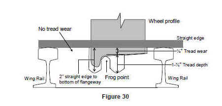
When a railroad wheel approaches the frog in the facing direction, the weight of the wheel is supported on the tread of the frog opposite the point until the wheel reaches the transition point, about 6 inches back from the actual point. At this location, the weight is transferred to the frog point.
137(d) Where frogs are designed as flange-bearing, flangeway depth may be less than that shown for Class 1 if operated at Class 1 speeds.
Guidance. This paragraph provides an exemption for an item of specialized track work that by design does not conform to the minimum flangeway depth requirements prescribed in paragraph (a) of this section. Called a flange-bearing frog, this technology is under consideration as a method of reducing impact loads at frogs. This design is a new concept for track above yard speeds but has been used extensively in light rail transit trackwork.
There are a number of frog designs in use throughout the
industry and the most common types are rail bound manganese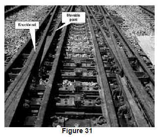 and bolted rigid
(stiff). The special attributes of spring frogs are covered under § 213.139.
Conventional moveable point frogs are found at flat angle track crossings and
slip switches (Figure 30). This type of movable point frog is similar to a
switch because of its movable points that fit against a knuckle rail, which is
like a stock rail.
and bolted rigid
(stiff). The special attributes of spring frogs are covered under § 213.139.
Conventional moveable point frogs are found at flat angle track crossings and
slip switches (Figure 30). This type of movable point frog is similar to a
switch because of its movable points that fit against a knuckle rail, which is
like a stock rail.
In recent decades, new technology movable frogs have been introduced in the Nation and there are two types—“swing nose” (Figure 31) and movable wing (Figure 32). Conventional movable point frogs and swing nose frogs are virtual switches; therefore there are no guardrails. As such, it is appropriate to use the applicable elements of § 213.135 (Switches) in an inspection report when encountering defects in these movable point frogs. For example, a movable point that does not fit its knuckle rail properly would be covered under § 213.135(b) (each switch point shall fit its stock rail properly).
The movable wing rail type frog is similar to a spring frog but both wing rails are moved remotely in synchronization with the switch points. It is appropriate to use the applicable elements of § 213.139 (Spring rail frogs) in an inspection report when encountering defects. Like above, when using any of the 139 series defect codes it is necessary to include 213 defect code 0133A15 – Turnout or track crossing fastenings not intact or maintained.
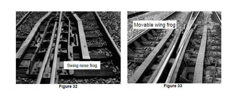
The following are the key elements to consider when inspecting new technology frogs:
• Bolting or fastener designs that fasten the movable point frog to concrete or timber switch ties are considered fasteners in the same manner as cut spikes. Fastenings are discussed under § 213.127 of this manual. Bolts that connect movable frog components together are considered frog bolts and must be addressed by using 213 defect code 0133A12, Loose or missing frog bolts.
• Of paramount importance is a proper fit of the vee point rails against the wing rails on movable frogs. Inspectors must use their judgment to determine if the point fits the wing rail properly to allow wheels to pass the frog point. Movements of the wing rail must not adversely affect the fit of the frog point to the wing rail. When an inspector encounters a condition on a movable frog which should be addressed on the inspection report and no existing code is available for that condition, 213 defect code 0137E will be acceptable with a full description of the condition in the inspection report.
• Unlike rail bound manganese frogs, the running surface of most, if not all, movable frogs are made of hardened rail. Inspectors must be aware that this rail may contain defects that require remedial action under § 213.113. Asymmetrical rails found in some switch points and frogs must be closely examined during inspections, as this appears to be a potential weak spot where a crack or break could occur.
• When performing inspections, FRA inspectors should discuss any concerns about an advanced turnout with appropriate railroad personnel. Inspectors should consult with the regional track specialist to resolve any questions about the safety of these installations.
General Guidance:. The various types of frogs available for specific applications include bolted rigid, solid manganese, self-guarded, railbound manganese, spring rail, movable point, cast, or swing nose. On railbound manganese frogs, the normal wear pattern is in the manganese insert.
An inspector, in addition to measurements described in the TSS, should see that a frog is supported throughout on well tamped and sound ties.
The requirements for flangeway depth in paragraph (a) and the requirements for tread wear in paragraph (c) also apply to crossing frogs. Since the designed flangeway depth is also 1⅞ inches, the safety concerns are the same, as excessive wear on the tread portion could result in a wheel flange striking the bottom of the flangeway and causing structural damage to the frog.
Inspectors must evaluate cracks or breaks in frog castings or rail defects in the non-running portion of wing rails in terms of their potential effect on the safe passage of rolling stock. In particular, when making the evaluation:
• The inspector should determine if there is a loss or imminent loss of wheel guidance due to a loss of functional integrity.
• The inspector should not consider cracks or breaks in a manganese frog casting that do not affect the safe passage of rolling stock to be a defective condition. If a severe crack, or a series of cracks, creates a condition where the breaking out of a piece of the casting is imminent, the use of 213 defect code 0137E should be considered. Cracks or wear that develop into a loss of functional integrity should be addressed by using 213 defect code 0137B or 0137C, which govern worn frog points and castings.
• Rail defects in the non-running portion of wing rails should be addressed by using 213 defect code 0137E.
§ 213.139 Spring rail frogs
139(a) The outer edge of a wheel tread shall not contact the
gage side of a spring wing rail.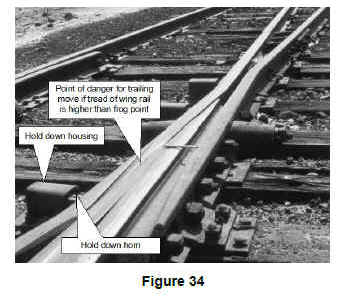
Guidance: : Inspectors must closely examine every spring rail frog encountered during an inspection. While spring rail frogs have been successfully used for many years, their unique design requires special maintenance attention to avoid derailment hazards to trailing point train movements on the main track. If a spring wing rail is higher than the top running surface of frog at the transition area, a wheel during a trailing move may push the spring wing rail open causing rail roll out or wide gage. Hollow or false flange wheels are more prone to cause this occurrence.
A beginning sign of outer edge wheel tread contact will appear as gouging on the gage corner of the wing rail behind the point of frog at the transition point similar to the stock rail/switch point configuration. While some spring frogs have a "relief" groove built into the frog for this purpose, inspectors must be acutely aware of any signs of the gage side of a spring wing rail being struck by the outer edge of wheel treads. Wheel gouging must not be confused with channeling in the spring wing rail that is incorporated at the time of manufacture to accommodate wheel tread transition. Vertical deflection at the toe of frog (213.139(b)) and hold-down housing clearance (213.139(e)) must be assessed when gage face wheel contact is observed. If the toe is not solidly tamped and excessive horn and housing clearance exists, the wing rail may have vertical motion while wheels are operating on the point rail in a trailing-point movement and the forces on the wing rail will cause the wing rail to move laterally, allowing the wheel to drop in at the throat of the frog.
139(b) The toe of each wing rail shall be solidly tamped and fully and tightly bolted.
Guidance: The toe of each spring rail frog must be solidly supported, and proper hold-down housing clearance must be maintained to avoid excessive vertical movement of the wing rail. The combination of these two conditions can cause outer edge wheel tread contact. The first sign that this is occurring will be gouging on the gage corner of the wing rail behind the point of frog. Wheel gouging must not be confused with channeling in the spring wing rail that is incorporated at the time of manufacture to accommodate wheel tread transition.
If the toe is not solidly tamped and excessive horn and housing clearance exists, the wing rail may have vertical motion operating on the point rail in a trailing-point movement and the forces on the wing rail will cause the wing rail to move laterally, allowing the wheel to drop in at the throat of the frog.
139(c) Each frog with a bolt hole defect or head-web separation shall be replaced.
Guidance. Any bolt hole defect or head-web separation in a spring frog of any dimension constitutes a defect. This paragraph does not prescribe a corrective action other than “replacement.”
139(d) Each spring shall have compression sufficient to hold the wing rail against the point rail.
Guidance: The intent of the regulation is to ensure the spring holds the wing rail against the point rail. Typically, if a wing rail is up against the point, it is an indication that the spring is holding it as intended. If an inspector finds the wing is not against the point he/she should determine the root cause of the condition. A component such as loose bolt may be obstructing the closure and 213.133A12 should be cited. Without proper anchorage, the horn may bind in the hold-down housing and defect 213.133B should be cited in classes 3-5. If there is a suspicion that there is insufficient compression in the spring, the railroad representative should determine its compliance.
139(e) The clearance between the hold-down housing and the horn shall not be more than ¼ inch.
Guidance. Since the spring wing rail is a movable part of a spring frog, it cannot be fastened down. The hold-down housing and a horn assembly prevents the wing rail from moving up higher than the top of the frog point. Figure 34 illustrates the proper method to determine if there is excessive space between the hold-down housing and the horn.
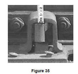 General
Guidance: Due to the
unique design characteristics of spring frogs, turnouts with this type of
appliance require special consideration in regard to guardrails. On the main
track side of a turnout, when trains are not "springing" the frog (by
design) and operating on an unbroken path, an extra length guardrail assures a
proper path for wheelsets.
General
Guidance: Due to the
unique design characteristics of spring frogs, turnouts with this type of
appliance require special consideration in regard to guardrails. On the main
track side of a turnout, when trains are not "springing" the frog (by
design) and operating on an unbroken path, an extra length guardrail assures a
proper path for wheelsets.
A guardrail should be of sufficient length to cover the designed hinge length. This keeps wheels off the spring wing rail from the point where this rail is "hinged" through the frog throat and finally to the actual frog point.
While the TSS does not address this design concept, inspectors should be aware of this attribute of spring frogs. If a guardrail is of insufficient length to cover the designed hinge length, any lateral wheel forces can cause significant problems. Specifically, the guardrail and other frog elements will quickly deteriorate, and in extreme circumstances, the wing rail can open while trains are moving through the main track side which can result in an unprotected wide gage. Inspectors should note on their inspection report any guardrail on a spring frog that is not of the proper length or installed in the improper position.
Another special consideration with regard to spring frogs is the longitudinal relationship between the spring wing rail and frog point. If a turnout has insufficient rail anchors to restrain longitudinal movement, the wing rail may not function properly. Evidence that longitudinal movement is occurring may be a gap between the wing rail and the frog point. Inspectors are reminded to refer to § 213.133(b) that requires Classes 3 through 5 track to be equipped with sufficient rail anchoring to restrict longitudinal rail movement. If longitudinal movement is observed because of insufficient anchors on Classes 1 and 2 track, inspectors are encouraged to note this condition and inform the railroad.
Spring frogs are manufactured with a steel base plate. Attached to the base plate are clip plates, which are placed along the fixed side of the frog. The clip plates, which are shaped into a right angle, are attached to the base plate by bolts, welds, or both. Frog bolts are placed through the body of the frog and through the vertical portion of the clip plates and tightened. This holds the body of the frog to the clip plate assembly.
There are no gage holding fasteners along the movable side of the frog as they would interfere with the spring wing rail. Therefore, it can be seen that the frog bolts and clip plate assemblies, acting together, maintain alinement of the spring frog. Care should be taken to ensure that the frog bolts and clip plate bolts are in place and tight (213 defect code 0133A12). Also check clip plates to see if welds are cracked or broken and check clip plates for cracks and breaks at the corner where the plate bends from horizontal to vertical. Where cracks or breaks in clip plates affect the fastening of the frog to the base plate, use defect
213 code 0133A15 (insufficient fasteners).
In recent years, railroads have augmented the design of spring frog installations by the application of improved stops to limit the amount of movement of the spring rail. In addition, some frogs have been retrofitted with welded stops. Most stops are designed to allow the wing to open no more than 1⅞ to 2¼ inches. When stops are properly installed, the risk of trailing point derailments is reduced.
When spring frogs are equipped with the improved features, such as relief grooves and stops, the inspector should evaluate the condition of the components in order to ascertain that the improved features are functioning as intended.
When spring frog defects are found, the defective conditions must be repaired as soon as possible. Combinations of the defects are especially hazardous. The railroad must protect the movements over the frog with a speed restriction until the defects are repaired.
Spring frog defects are considered as non-class-specific defects (see § 213.9); therefore, inspectors must consider the circumstances involved in evaluating the remedial action taken by the railroad when spring frog defects are found. Inspectors should consider all spring frog defects as serious defects that must be repaired as soon as possible. In most circumstances, when it is evident that the outer edge of the wheels are contacting the gage side of the wing rail or a combination of spring frog defects exist, inspectors would expect that the railroad would implement a speed restriction.
Some spring frogs are equipped with retarders that reduce the impact of the wing on the point as the wing closes with each passing wheel in the diverging route. The retarders may hang, causing the wing to remain open. Though the TSS does not address this design concept, inspectors should still be aware of this attribute of spring frogs because it could lead to further degradation of frog components.
§ 213.141 Self-guarded frogs
141(a) The raised guard on a self-guarded frog may not be worn more than
⅜ of an inch.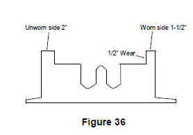
Guidance. When examining self-guarded frogs, observe the condition of the frog point, and where there is evidence of wear caused by wheel flanges contacting the frog point, take measurements to determine compliance with this section. To determine the amount of wear on a raised guard, measure the thickness at a portion where there is wear. Compare this measurement to a portion where there is no wear and the difference between the two is equivalent to the amount of wear.
141(b) If repairs are made to a self-guarded frog without removing it from service, the guarding face must be restored before rebuilding the point.
Guidance. During repairs of a self-guarded frog, it is imperative that the raised guarding face is restored before the actual frog point. This precaution is necessary due to the potential for a wheel flange striking the frog point.
Self-guarded frogs are designed for use in low speed track and their use in tracks where speeds exceed 20 mph can result in excessive lateral forces such as wheels “kicking” or in extreme cases wheels climbing up the raised guard. The TSS does not prohibit the use of self-guarded frogs in any class of track; however, inspectors are encouraged to inform a railroad of the potential for problems that may occur if a self-guarded frog is found in a track where speeds exceed 20 mph.
§ 213.143 Frog guard rails and guard faces; gage
The guard check and guard face gages in frogs must be within the limits prescribed in the following table:
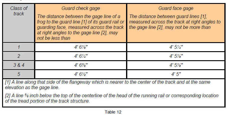


Guidance. A guardrail is installed parallel to the running rail opposite a frog to form a flangeway with the rail and to hold wheels of equipment to the proper alinement when passing through the frog.
A guardrail must be maintained in the proper relative position to the frog in order to accomplish its critical intended safety function. Inspectors should examine guardrails carefully to see that they are adequately fastened, and when measuring guardrail gage, fully consider any movement of guardrail or frog under traffic conditions.This section clearly specifies allowable tolerances for guard check and guard face gage for various classes of track.
When measuring guard check gage, it is important to consider the path of wheels through the frog because the function of a guardrail is to keep wheel flanges from striking the actual frog point. As reference, standard check gage on a railroad wheel set is approximately 54½ inches (see Figure 36 for approximate design check gage values). While the TSS minimum guard check gage is less than wheel check gage in lower classes of track, the condition of the actual frog point in relation to the path of wheels through a frog is a good indicator of the effectiveness of a guardrail.
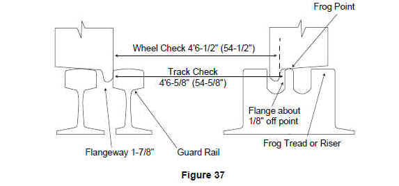
The critical area where guard check gage must be measured is at the actual point of frog. Inspectors must also consider any unusual wear that may exist at the actual frog point and position the track gauge or other measuring device accordingly.
When measuring guard check gage, dynamic lateral movement of the guardrail and/or frog shall be considered. In the case of a frog that is moving laterally under train movement (floating), it is important to consider the most restrictive measurement. Specifically, if measuring guard check gage in a turnout where the frog can move toward the track being measured due to train movement on the other track, that dynamic frog position would be considered. See the figure below.
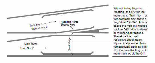
In severe cases, where a frog is severely floating (moving laterality under load) and there is an accompanying condition (i.e., deteriorated crossties or ineffective fasteners), FRA inspectors should cite the defect or recommend a civil penalty for the accompanying condition (i.e., §§ 213.109 (Crossties) or 213.127 (Rail fastenings)).
Face gage is a dimension that becomes critical when the distance between two opposing guardrails, or a guardrail and a frog wing rail, become larger than the distance between the back of wheelsets. This would occur by improper installation, or a condition such as a severe alinement defect. Normally, face gage would be measured in the same vicinity as check gage. However, inspectors should consider measuring face gage at other points in special trackwork where there may be an indication that wheels are being "pinched." For general reference, the following illustrates approximate design face gage values.
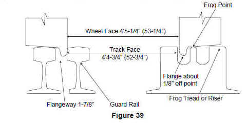
Broken guardrails occur infrequently, since they do not support the vertical wheel loads of passing trains. When evaluating a crack or break in a guardrail, the inspector should be aware that cracks or breaks exist that do not affect the ability of the guardrail to function as intended. If the integrity of the guardrail is affected, the inspector will cite the defect using 213 defect code 0143A3, Cracked or broken guardrail.
There are many different types and designs of frog guardrail designs. Some guardrail plates are recessed to seat the running rail, while others are flat. Some guardrail plates are punched with spike-hole slots; others are not. Other guardrails are bolted to the running rail. On some railroads, it is normal practice not to spike the gage side of the running rail through the guardrail area while some guardrail plates do not have holes punched for this purpose. FRA has no record of serious safety problems that have developed as a result of not spiking the running rail through the guardrail area.
If encountering a problem where the running rail has moved laterally to create an unsafe condition, the inspector should use insufficient fasteners defect code 213.127. Inspectors should discuss unique situations with their regional track specialist.
While not a requirement of the TSS, guardrails have a straight portion that guides wheels through the area from the “throat” to the actual frog point. If inspectors find a guardrail where the straight portion does not encompass this area, inspectors should bring this to the attention of the railroad. Figure 39 illustrates the proper measurement points to determine check/face gage compliance and shows the proper longitudinal relationship between a guardrail and frog point.
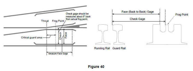
- ARC-Tech.Net internet websites
- ww.railroadtraining.net
- PO Box 206, Kingsbury, IN 46345
- 512-553-6226
- Source Study Manual and Rules Book information provided by the Federal Railroad Administration.
- Presentation Copyright © 2007-2018 ARC-Tech.Net. All rights reserved.